


 252 / 338

D-18
Additional information
Designing horizontal busbars
Linergy BS
Electrical characteristics
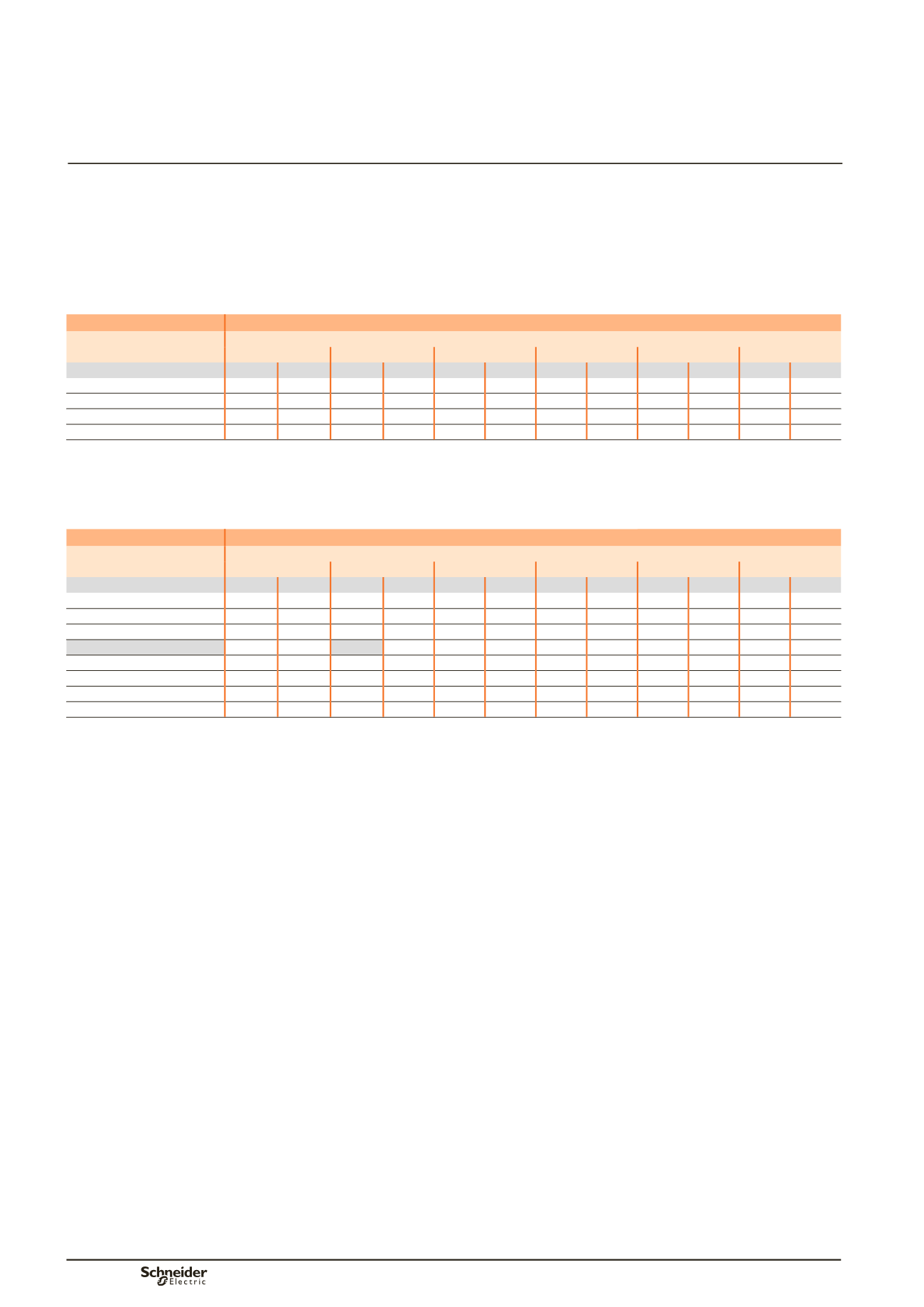
Permissible current and selection of horizontal busbar
The goal is to optimise busbar size according to the installation and operating
criteria.
Up to 1600 A
Linergy BS bars, 5 mm thick
Type of bars
Permissible current (A)
Ambient temperature around the switchboard
25 °C
30 °C
35 °C
40 °C
45 °C
50 °C
Size per phase
IP
y
31 IP > 31 IP
y
31 IP > 31 IP
y
31 IP > 31 IP
y
31 IP > 31 IP
y
31 IP > 31 IP
y
31 IP > 31
1 Linergy BS bar, 60 x 5
890
840
850
790
800
750
760
700
710
650
660
bb
1 Linergy BS bar, 80 x 5
1130 1050 1080 990
1000 900
970
870
910
810
860
bb
2 Linergy BS bars, 60 x 5
1580 1420 1500 1350 1400 1250 1350 1180 1260 1090 1180
bb
2 Linergy BS bars, 80 x 5
2010 1820 1920 1720 1800 1600 1720 1510 1610 1390 1510
bb
bb
Connection impossible due to the operating-temperature limits of the devices installed in the switchboard.
Up to 3200 A
Linergy BS bars, 10 mm thick
Type of bars
Permissible current (A)
Ambient temperature around the switchboard
25 °C
30 °C
35 °C
40 °C
45 °C
50 °C
Size per phase
IP
y
31 IP > 31 IP
y
31 IP > 31 IP
y
31 IP > 31 IP
y
31 IP > 31 IP
y
31 IP > 31 IP
y
31 IP > 31
1 Linergy BS bar, 50 x 10
1330 1220 1260 1160 1200 1080 1130 1010 1060 940
990
bb
1 Linergy BS bar, 60 x 10
1550 1400 1470 1320 1400 1250 1320 1160 1240 1070 1160
bb
1 Linergy BS bar, 80 x 10
1990 1800 1890 1700 1800 1600 1700 1500 1600 1390 1500
bb
2 Linergy BS bars, 50 x 10
2270 2090 2160 1980 2050 1850 1930 1740 1810 1610 1690
bb
2 Linergy BS bars, 60 x 10
2550 2270 2420 2140 2300 2000 2170 1870 2030 1720 1900
bb
2 Linergy BS bars, 80 x 10
3110 2820 2970 2660 2820 2500 2660 2330 2500 2160 2330
bb
2 Linergy BS bars, 100 x 10
3650 3280 3490 3100 3300 2900 3130 2720 2950 2510 2750
bb
2 Linergy BS bars, 120 x 10
4160 3760 3960 3550 3760 3340 3560 3100 3340 2880 3120
b
bb
Connection impossible due to the operating-temperature limits of the devices installed in the switchboard.
Example:
Two 50 x 10 mm bars can be used for a 2160 A current with an IP
y
31 and an
ambient temperature of 30 °C around the switchboard.
Where possible, use of 10 mm bars is worthwhile in terms of the In/Isc:
bb
gain in time during switchboard mounting given, where applicable, the lesser
number of bars installed
bb
for short-circuits, the rigidity of the bars means fewer busbar supports.
Recommendation:
Use 5 mm bars for In
y
1600 A and low Icw values (40 kA rms).
Use 10 mm bars for In > 1600 A and medium to high Icw values (> 40 kA rms).
Note:
the values indicated above have been validated for Prisma P switchboards.