


 249 / 338

D-15
Additional information
Designing Prisma P
power circuits
Presentation and approach
Electrical characteristics
Busbars
The maximum load current for a set of busbars is a function of the thermal
environment.
The type and the size of the conductors must be determined in view of carrying the
required currents taking into account the temperatures reached in the switchboard.
These conductors are subjected to additional heat rise caused by the flowing current
(joule effect) and the connected devices.
The temperatures reached by the conductors and the insulating materials, etc. must
not exceed the maximum temperatures for which the products were designed.
Schneider Electric busbars and distribution blocks are sized to operate without any
particular constraints for the assemblies in Prisma P switchboards operating under
normal environmental conditions (standard switchboard configuration, 35 °C outside
the switchboard, etc.).
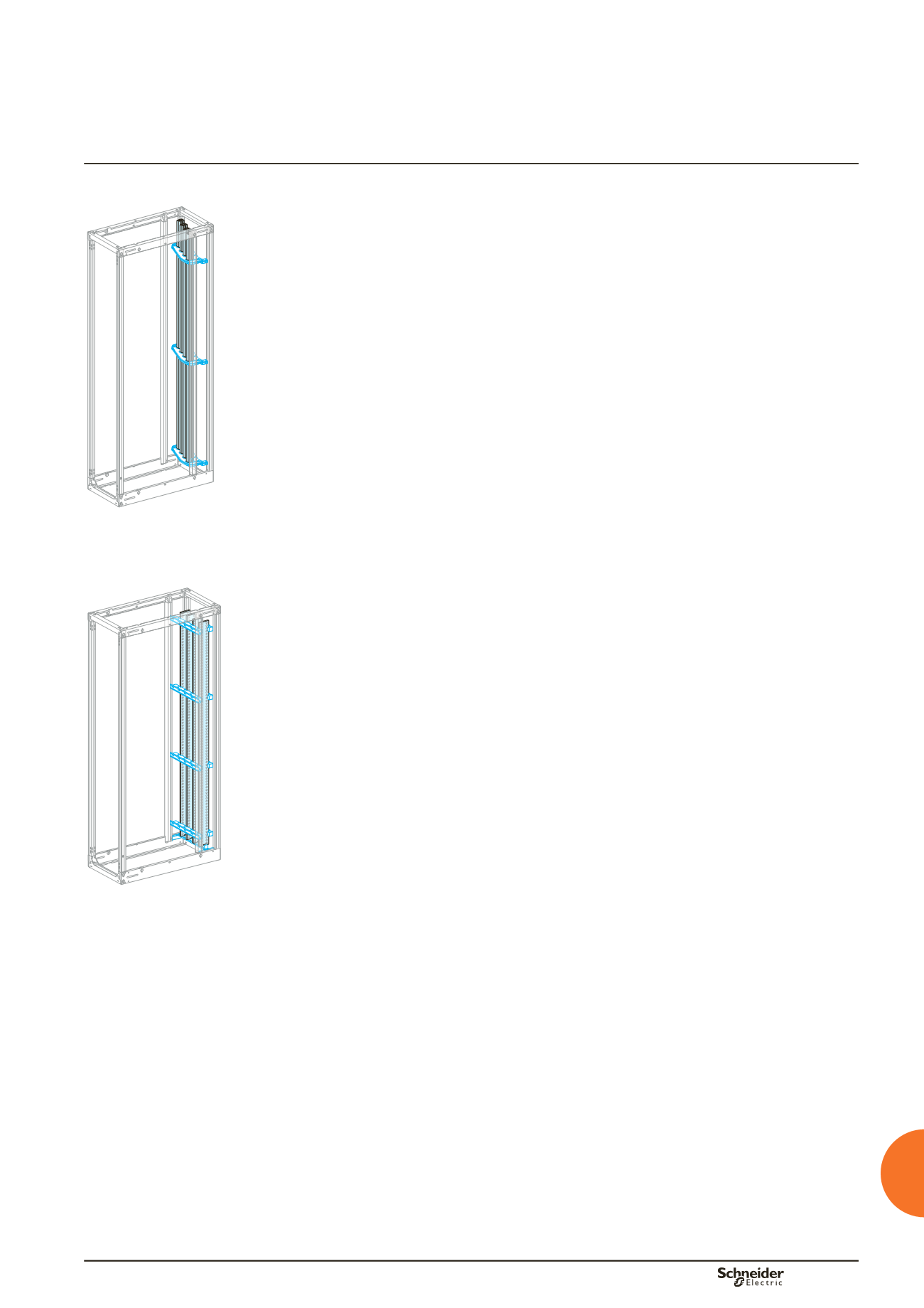
DD381459.eps
To determine the
Linergy LGY busbars
or
Linergy LGYE
required, see the tables
on pages D-17, D-19 et D-20.
They can be used to determine:
b
the type of Linergy LGY busbars or Linergy LGYE, as a function of:
v
the current
v
the IP value
v
the ambient temperature around the switchboard
v
ICW/1s.
bb
Linergy LGY
busbars:
I
y
1600 A.
bb
Double Linergy LGY
busbars:
1600 A < I
y
3200 A
bb
Linergy LGYE
busbars:
y
4000 A.
DD381460.eps
To determine the required
Linergy BS busbars
, see the tables on pagepage D-18
(horizontal busbars) and page D-21 (vertical busbars).
They can be used to determine:
b
the permissible current as a function of:
v
the size of the busbars
v
the number of bars
v
the ambient temperature around the switchboard
v
the IP value
v
Icw/1s.
b
Linergy BS copper busbars
5 mm thick: I
y
1600 A.
b
Linergy BS copper busbars
10 mm thick: I
y
3200 A.
Connection of devices
u
630
and busbar connections
To determine the
size of upstream and downstream connections
for devices,
see the tables starting on pagepage D-23.
They can be used to determine:
b
the size of copper busbars
b
the maximum permissible current.
As a function of:
b
the type of circuit breaker
b
the IP value
b
the ambient temperature around the switchboard
b
the type of installation.