


 250 / 338

D-16
Additional information
Designing Prisma P
power circuits
Presentation and approach
Electrical characteristics
Designing the PE protective
conductor
The protective conductor must be sufficiently sized and securely installed in the
switchboard to accept the thermal and electrodynamic constraints of the fault
current.
It must be connected to the exposed conductive parts of the switchboard.
It must be accessible to enable connections both in the factory and on site.
Optimised calculation method
Use the calculation equation indicated in standard IEC 60439-1 and 2:
S
PE
= l
2
t
k
b
SPE: cross-sectional area of the PE in mm²
b
I: value of the phase-to-earth fault current = 60 % of the value of the
phasetophase
b
fault current (IEC 60439-1 §8.2.4.2)
b
t: time the fault current flows in seconds
b
k: coefficient that depends on the type of metal, k = 143 for a copper
conductor with PVC insulation.
Example:
v
Isc = 36 kA rms C the value of the phase-to-earth fault current = 60 % of the value
v
of the phase-to-phase fault current (standard IEC 61439-1 and 2 § 8.4.3.2.3 and
10.11.5.6), i.e.: 36 x 0.6 = 21.6 kA
v
maximum time delay for the control unit: 0,5 s
v
k = 143 for copper conductors with PVC insulation.
The calculation is therefore:
v
v
S
PE
= 21600
2
x 0,5 = 106,8 mm
2
143
The PE conductor must therefore be a 25 x 5 mm bar (= 125 mm
2
).
Simplified method (based on the equation above)
Use the table below to determine the size of the PE conductor as a function ofdevice
short-circuit current Isc.
Size of PE conductor
All Schneider Electric devices
Isc
y
40 kA
1Linergy BS bar, 25 x 5 mm
Isc
y
65 kA
1Linergy BS bar, 50 x 5 mm Linergy LGY 630 -
04502
Isc > 65 kAmais < 80 kA
1Linergy BS bar, 50 x 5 mm Linergy LGY 800 -
04503
Isc = 100 kA
1Linergy BS bar, 50 x 5 mm Linergy LGY 1000 -
04505
DD381471.eps
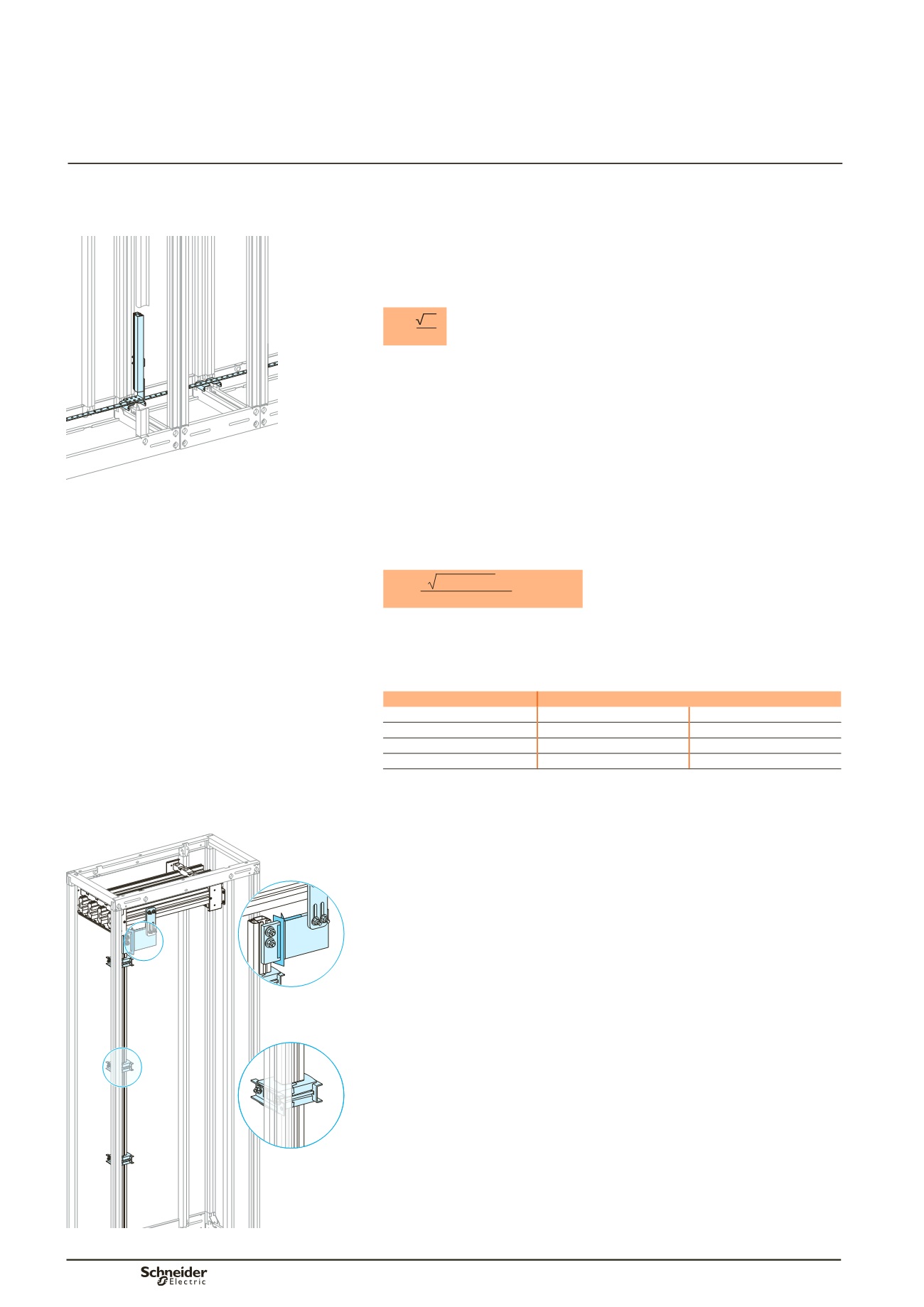
Implementing the PEN protective
conductor
The size of the PEN is determined in the same manner as a neutral conductor, i.e.:
bb
for copper single-phase circuits or sized
y
16mm², it must be the same size as the
phase conductors
bb
for copper three-phase circuits sized > 16 mm², it can be:
vv
the same size as the phase conductors
vv
smaller on the condition that:
- the current likely to flow in the neutral during normal operation is less than the
permissible current for the conductor
- the power rating of single-phase loads does not exceed 10 % of the total rating.
The conductor must be accessible to enable connections both in the factory and
on site, as well as checks on the tightness of connections.
DD384616.eps
Installation du conducteur de protection PEN
According to standard IEC 61439-1 and 2, the practical guidelines for implementing
the PEN are the following:
bb
at the entry to the assembly, the PEN connection must be next to the phase
connections
bb
within the assembly, the PEN does not need to be insulated from the exposed
conductive parts (except on sites where there is a risk of fire or explosion)
bb
the size of the conductor must be at least equal to that of the neutral
bb
the size must remain constant throughout the main busbars
bb
the change from a TNC to a TNS system must take place at a single point in the
switchboard, via a marked neutral-disconnection bar that is accessible and can be
dismantled to facilitate the impedance measurement of the fault loop
bb
after the TNS creation point, it is forbidden to recreate a TNC system.
The PE and the neutral must meet their specific requirements.
Linergy LGY PEN kit
See page B-49.