


 520 / 759

 mkelectric.co.uk
520
Installation (TV sockets)
Product performance, systems compatibility
Isolated Outlets are intended for use where safety isolation (rated
at 2000V ac) is required to provide protection against faults
occurring within any mains powered product used on different
parts of the distribution system. They are not suitable for use in
systems where DC signals are passed through the socket, (e.g.
where masthead/headend equipment is controlled by receiver/
decoder equipment).
Diplexer Outlets are used in distribution systems where both TV
and FM band signals are combined on a single aerial downlead.
The filtering in the diplexer separates the appropriate signals and
feeds them through to the relevant output connection port.
Cable Routing and Use of Cable Clamp
Sharp bends in the cable must be avoided during installation. The
single TV/FM socket is fitted with a cable clamp that can be fixed
on either side of the termination position to facilitate this.
When tightening the screening braid clamps ensure that the cable
is firmly gripped and that the inner insulation is not squashed flat
beyond a slight oval shape.
Safety Information
TV outlets or modules must not be installed in the same enclosure
as equipment rated in excess of 50V, (e.g. mains rated 13A
sockets or switches).
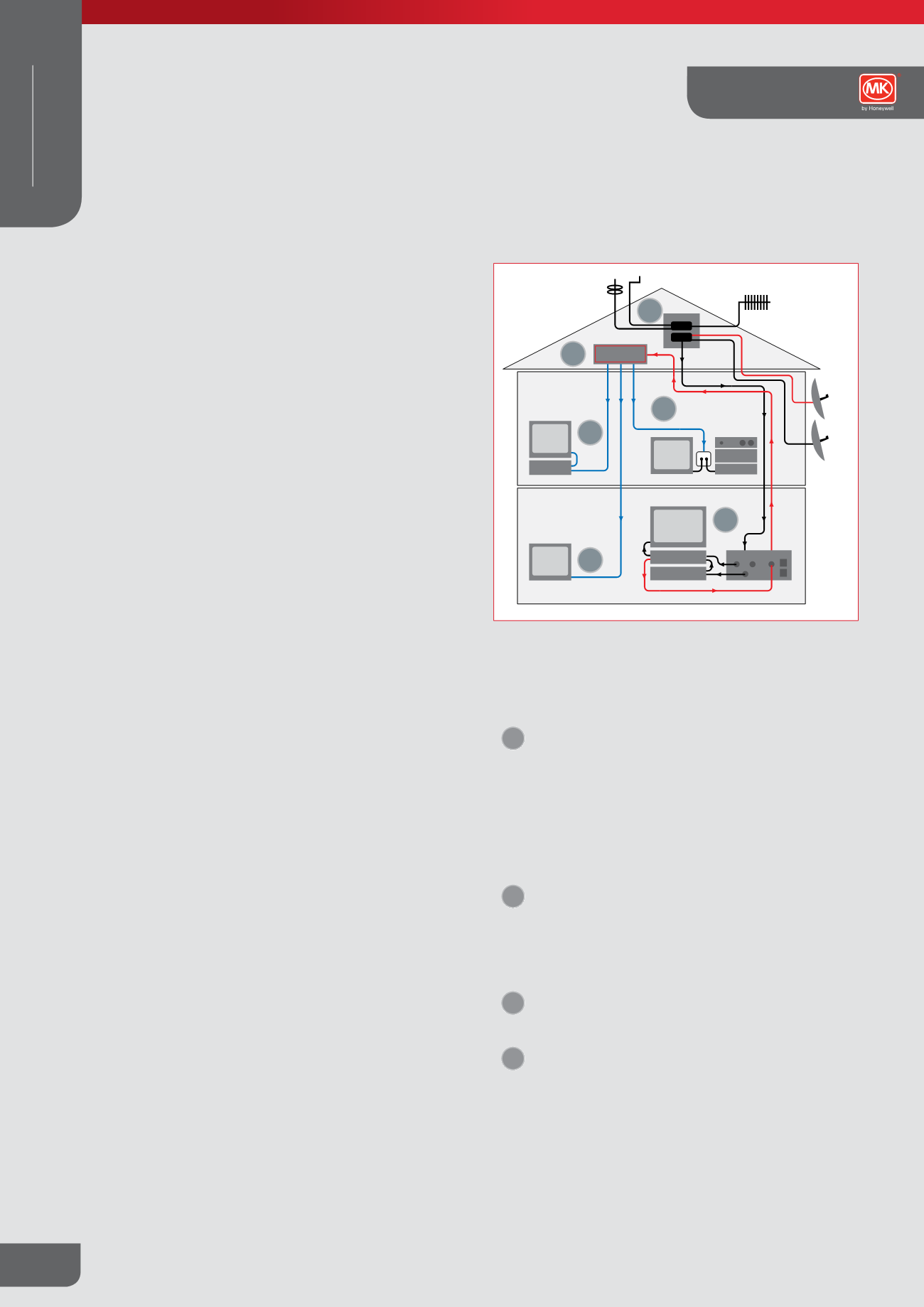
TV/FM and Satellite Socket Outlets
Method of installation of TV and FM aerial connection by using MK
co-axial socket outlet and only one downlead.
Conventional distribution system for TV and FM signals using a
single aerial downlead.
1
The signals from the TV and FM aerials and the satellite
dish are combined together using two products. The
first combines the TV and FM signals and the second
adds the Sky signal to the TV/FM signal and provides
a DC control path to power the LNB unit on the satellite
dish. (These products are not supplied by MK).
The single aerial down lead feeds into the triplexer
(black lines in wiring diagram).
2
The separated satellite signal is then fed to the decoder.
The decoded satellite signal is then fed into the VCR
along with the TV signal from the Triplexer. The output
signal from the VCR then feeds into the TV and also
back to the single outlet and onto the distribution
amplifier (black lines in wiring diagram).
3
The single cable back-feed then feeds back to the input
of a multi way distribution amplifier, (typically located in
the loft or garage) (red lines in wiring diagram).
4
Each individual output from the distribution amplifier
is then fed to the individual rooms in the house to a
standard TV (single or diplexer) outlet to which the TV/
VCR and/or Hi-Fi can be connected (blue lines in wiring
diagram).
FM
TV
SAT 1
DAB
TV
TV
TV
TV
VID
SKY/DIG
VID
TV DIST
HI-FI
SAT 2
1
4
4
4
2
3
Elements Collection
Technical
WIRING DEVICES
DECORATIVE