


 509 / 759

Technical Hotline
+44 (0)1268 563720
509
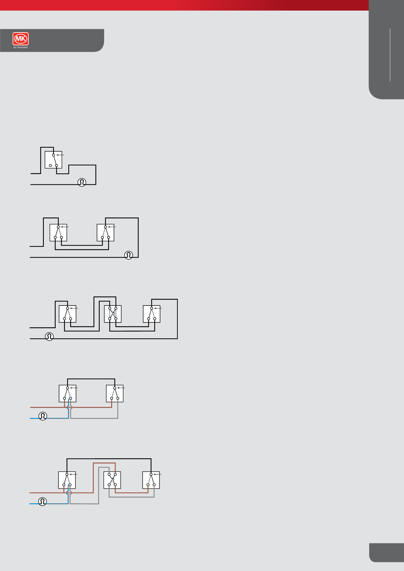
Grid Switch Modules
Wiring Diagrams
One-way switching
N
L
1
Common
Lamp/s
N
L
Lamp/s
2
1
Common
1
2
Common
Two-way switches
Dotted lines show alternative switch positions
N
L
2
1
Common
2
1
Common
Two-way switches
Dotted lines show alternative switch positions
Lamp/s
SW.L
L
N
L
1
2
Common
2
1
Common
Two-way
switch
Two-way
switch
Dotted lines show alternative switch positions
Lamp/s
1
1
2
2
1
1
2
2
Intermediate
switch
2
1
Common
2
1
Common
Two-way
switch
Two-way
switch
Dotted lines show alternative switch positions
Intermediate
switch
N
Lamp/s
SW.L
Two-way switching – 2 wire control
N
L
1
Common
Lamp/s
N
L
Lamp/s
2
1
Common
1
2
Common
Two-way switches
Dotted lines show alternative switch positions
N
L
2
1
Common
2
1
Common
Two-way switches
Dotted lines show alternative switch positions
Lamp/s
SW.L
L
N
L
1
2
Common
2
1
Common
Two-way
switch
Two-way
switch
Dotted lines show alternative switch positions
Lamp/s
1
1
2
2
1
1
2
2
Intermediate
switch
2
1
Common
2
1
Common
Two-way
switch
Two-way
switch
Dotted lines show alternative switch positions
Intermediate
switch
N
Lamp/s
SW.L
Two-way switching – 3 wire control
N
L
1
Common
Lamp/s
N
L
Lamp/s
2
1
Common
1
2
Common
Two-way switches
Dotted lines show alternative switch positions
N
L
2
1
Common
2
1
Common
Two-way switches
Dotted lines show alternative switch positions
Lamp/s
SW.L
L
N
L
1
2
Common
2
1
Common
T o-way
switch
Two-way
switch
Dotted lines show alternative switch positions
Lamp/s
1
1
2
2
1
1
2
2
Intermediate
switch
2
1
Common
2
1
Common
Two-way
switch
Two-way
switch
Intermediate
switch
Two-way switching plus intermediate switching
– 2 wire control
N
L
1
Common
Lamp/s
N
Lamp/s
2
1
Common
1
2
Common
Two-way switches
Dotted lines show alternative switch positions
N
L
2
1
Common
2
1
Common
Two-way switches
Dotted lines show alternative switch positions
Lamp/s
SW.L
N
L
1
2
Common
2
1
Common
Two-way
switch
Two-way
switch
Dotted lines show alternative switch positions
Lamp/s
1
1
2
2
1
1
2
2
Intermediate
switch
2
1
Common
2
1
Common
Two-way
switch
Two-way
switch
Dotted lines show alternative switch positions
Intermediate
switch
N
Two-way switching plus intermediate switching
– 3 wire control
N
L
1
Common
Lamp/s
N
L
Lamp/s
2
1
Common
1
2
Common
Two-way switches
Dotted lines show alternative switch positions
N
L
2
1
Common
2
1
Common
Two-way switches
Dotted lines show alternative switch positions
Lamp/s
SW.L
L
N
L
1
2
Common
2
1
Common
Two-way
switch
Two-way
switch
Dotted lines show alternative switch positions
Lamp/s
1
1
2
2
1
1
2
2
Intermediate
switch
2
1
Common
2
1
Common
Two-way
switch
Two-way
switch
Dotted lines show alternative switch positions
Intermediate
switch
N
Lamp/s
SW.L
Note: Terminal positions may alter. The above diagrams are to show
wiring layout.
Note:
Switches featuring locators and indicators use LED illumination.
All switches fitted with a locator are intended to give a very low
light output whilst the switch is turned off. The low level of power
flowing in this circuit is compatible with the majority of installation
requirements however, certain lamp types or installations using
multiple intermediate switches on one circuit may require the use of
a snubber capacitor. The recommended capacitor to use would be
X2 rated 275V 0.1 µ F.
Switches incorporating indicator or locator illumination must be
disconnected before carrying out any site installation testing.
Elements Collection
Technical
WIRING DEVICES
DECORATIVE