


 220 / 582

BETA Protecting
Low-Voltage Fuse Systems
3
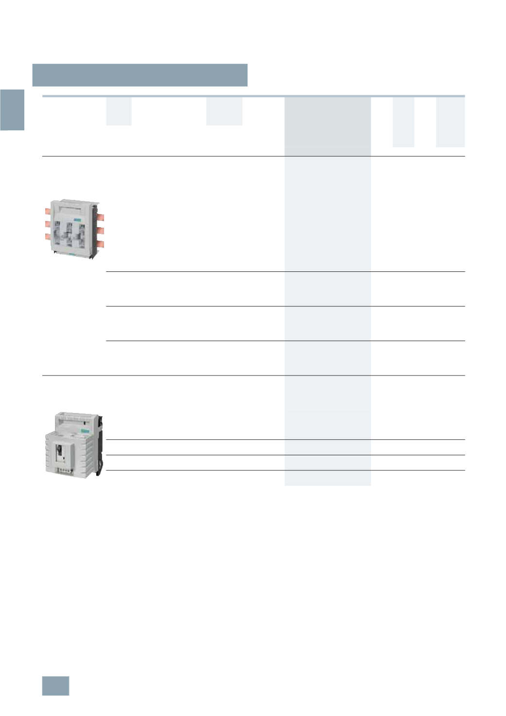
NP LV HRC fuse switch disconnectors
3/70
Siemens ET B1 · 10/2008
3
*
You can order this quantity or a multiple thereof.
All fuse switch disconnectors with flat terminals must be used
with the appropriate cable lug covers (3NY7 101 to 3NY7 141)
for finger-safe cover according to BGV A2,
see page 3/76
.
1)
See LV HRC Fuse Links.
2)
Insert silver-plated isolating links.
3)
Can only be mounted on 5 mm thick busbars, a busbar thickness compensator
is required for 3NP42 and 3NP43;
see page 3/77
.
3
NP44 can only be mounted on busbars with a thickness of 10 mm!
4)
No further cover required for 3NP40 with box terminal.
5)
SIRIUS motor starter protector with auxiliary switch 1 NO + 1 NC as stan-
dard. 3NP40 7 also available with auxiliary switch 2 NOs or 2 NCs on
request.
6)
For 3NP40 7 with output socket for auxiliary switch, the signal lead must be
ordered separately,
see page 3/77
.
In the case of 3NP41 to 3NP44, the
auxiliary switch must be connected over a 2.8 mm
×
0.5
mm flat terminal
according to DIN 46244-A.
Rated
residual
current
Connection type
(
double-ended)
For LV HRC
fuse links
acc. to
DIN 43620
1)
For
isolating
links
2)
Degree of protection IP00,
without fuse links,
without isolating links,
with terminal screws
I
u
Connection For
conductor
cross-section
DT Order No.
Price
per PU
PG PU PS*/
P. unit
Weight
per PU
approx.
A
mm
2
Size
Size
Unit(s) Unit(s) kg
For 60 mm busbar system
For busbars of width 12 mm or 30 mm and
thickness 5 mm or 10 mm
3)
As flat, T and I profiles,
as well as Rittal PLS systems
160
Flat terminals Up to 2
×
70 (
M8)
Connection,
top
00
a. 000 00
A
3
NP40 76-1CE01
103 1
1
1.203
Connection,
bottom
}
3
NP40 76-1CF01
103 1
1
1.201
Box
terminals
4)
2.5 ... 70
or
2
×
2.5 ... 16
Connection,
top
00
a. 000 00
B
3
NP40 76-1CK01
103 1
1
1.295
Connection,
bottom
}
3
NP40 76-1CJ01
103 1
1
1.249
250
Flat
terminals
Up to 150 (M10)
Connection,
top or
bottom
1
and 0 1 and 0
}
3
NP42 76-1CG01
103 1
1
3.713
400
Flat
terminals
Up to 240 (M10)
Connection,
top or
bottom
2
and 1 2 and 1
}
3
NP43 76-1CG01
103 1
1
5.440
630
Flat
terminals
Up to 2
×
240 (
M12)
Connection,
top or
bottom
3
and 2 3 and 2
}
3
NP44 76-1CG01
103 1
1
7.688
Surface mounting and installation
With fuse monitoring by
SIRIUS motor starter protector
5) 6)
Up to 160 A, also clip-on for standard mounting rail
160
Flat terminals Up to 2
×
70 (
M8)
00
a. 000 00
A
3
NP40 70-0FA01
103 1
1
1.276
Box terminals 2.5 ... 70 or
2
×
2.5 ... 16
A
3
NP40 70-0FH01
103 1
1
1.350
250
Flat terminals Up to 150
(
M10)
1
and 0 1 and 0 A
3
NP42 70-0FA01
103 1
1
2.940
400
Flat terminals Up to 240
(
M10)
2
and 1 2 and 1 A
3
NP43 70-0FA01
103 1
1
4.174
630
Flat terminals Up to 2
×
240 (
M12)
3
and 2 3 and 2 A
3
NP44 70-0FA01
103 1
1
5.495
© Siemens AG 2008