


 223 / 582

BETA Protecting
Low-Voltage Fuse Systems
3
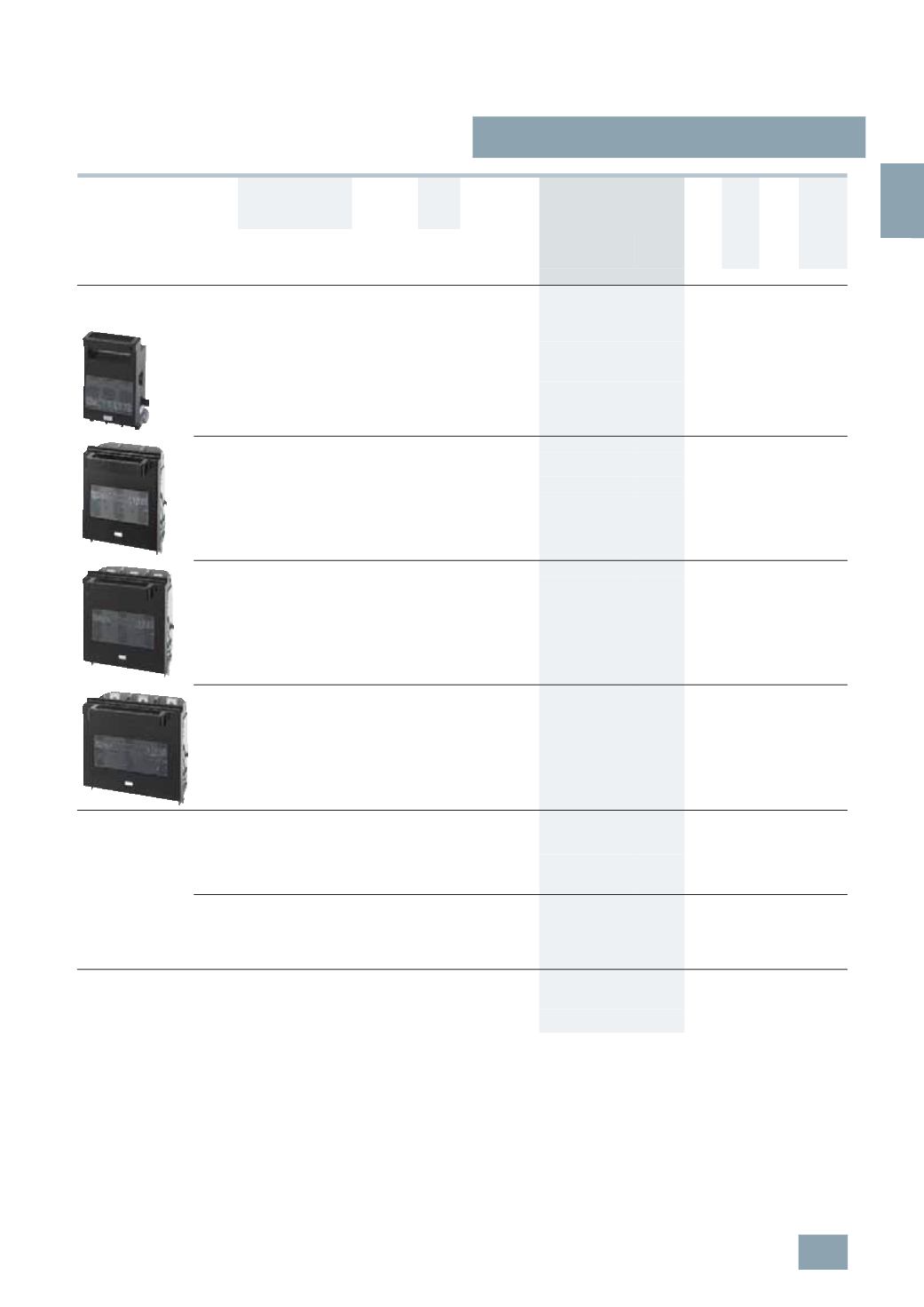
NP LV HRC fuse switch disconnectors
3/73
Siemens ET B1 · 10/2008
3
*
You can order this quantity or a multiple thereof.
1)
See LV HRC Fuse Links.
2)
The relevant 3NY1 106 cable lug covers must be used for 3NP50 60 with
flat terminals (see Accessories) for the purpose of protection against
accidental contact according to DIN VDE 0106-100
(
see page 3/76)
.
3)
According to DIN 46234 or 16 mm
2
... 95
mm
2
according to DIN 46235
(
use M10 cable lug if necessary).
4)
If auxiliary switch is retrofitted, additional drill holes are required on the switch.
5)
According to DIN 46234 or DIN 46235; with cable lug according to
DIN 46235; conductor cross-section min. 16 mm
2
(
use M12 cable lug if
necessary).
6)
According to DIN 46234 or 16 ... 95 mm
2
according to DIN 46235
(
use M cable lug if necessary).
Rated
residual
current
Connection type
(
double-ended)
For LV HRC
fuse links
acc. to
DIN 43620
1)
For
isolating
links
AS on
switch
disconnector
Degree of protection IP00,
without fuse links,
without isolating links,
with terminal screws
I
u
Connection For
conductor
cross-section
DT Order No.
Price
per PU
PG PU PS*/
P. unit
Weight
per PU
approx.
A
mm
2
Size
Size
Unit(s) Unit(s) kg
For surface mounting and installation on and in distribution
boards completely compartmentalized,
with high speed closing feature
160
Flat
terminals
2)
2.5 ...150
3)
00
a. 000 00
Without
4)
}
3
NP50 60-0CA00
103 1
1
1.608
1
NO +
1
NC
B
3
NP50 60-0CA10
103 1
1
1.650
Clamp
terminals
1-
wire 00 a. 000 00
Without
4)
A
3
NP50 60-0CB00
103 1
1
1.739
2.5 ... 50
or
2
conductors
1
×
2.5 ... 50
1
×
2.5 ... 35
1
NO +
1
NC
B
3
NP50 60-0CB10
103 1
1
1.748
250
Flat
terminals
6 ... 150
5)
1
and 0 1
Without
}
3
NP52 60-0CA00
103 1
1
5.475
1
NO +
1
NC
A
3
NP52 60-0CA10
103 1
1
5.491
Clamp
terminals
35 ... 120 1
and 0 1
Without
C
3
NP52 60-0CB00
103 1
1
5.605
1
NO +
1
NC
B
3
NP52 60-0CB10
103 1
1
5.814
400
Flat
terminals
6 ... 240
5)
2
and 1 2
Without
}
3
NP53 60-0CA00
103 1
1
6.532
1
NO +
1
NC
A
3
NP53 60-0CA10
103 1
1
6.551
630
Flat
terminals
2
×
6 ... 240
5)
3
and 2 3
Without
}
3
NP54 60-0CA00
103 1
1
7.945
1
NO +
1
NC
B
3
NP54 60-0CA10
103 1
1
7.958
For 40 mm busbar system
Completely compartmentalized, with high speed closing
6)
Busbar width: 12 mm and 5 mm or 10 mm thickness
160
Flat
terminals
2.5 ...150
3)
00
a. 000
Without
C
3
NP50 65-1CF00
103 1
1
2.380
Connection,
bottom
1
NO +
1
NC
B
3
NP50 65-1CF10
103 1
1
2.370
Clamp
terminals
1-
wire 00 a. 000
Without
B
3
NP50 65-1CG00
103 1
1
2.433
2.5 ... 50
or
2
conductors
1
×
2.5 ... 50
1
×
2.5 ... 35
bottom connection
1
NO +
1
NC
B
3
NP50 65-1CG10
103 1
1
2.437
For 60 mm busbar system
Surface mounting and installation completely compartmentalized,
with high speed closing
Use switch version "Surface mounting and installation" and
busbar adapter,
see page 3/82
.
© Siemens AG 2008