


 226 / 582

BETA Protecting
Low-Voltage Fuse Systems
3
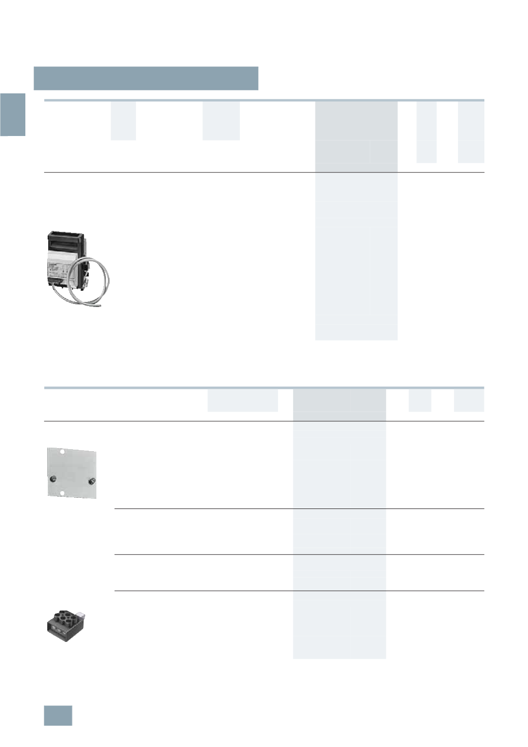
NP LV HRC fuse switch disconnectors
3/76
Siemens ET B1 · 10/2008
3
*
You can order this quantity or a multiple thereof.
1)
See LV HRC Fuse Links
.
2)
According to DIN 46234 or 16 mm
2
... 95
mm
2
according to DIN 46235
(
use M10 cable lug if necessary).
All fuse switch disconnectors with flat connections must be used with the relevant cable lug covers (3NY7 101 to 3NY7 141) in order
to ensure protection against finger touch according to BGVA3, see the following table.
1)
The fuse switch disconnector with mounted cable lug covers, together with
molded-plastic covers for distributor/device field/incoming feeder unit, is
easy to install in the meter cabinet.
Rated
residual
current
Connection type
(
double-ended)
For LV HRC
fuse links
acc. to
DIN
43620
1)
Auxiliary switches
Degree of protection IP00,
without fuse links,
without isolating links,
with terminal screws
On
On
I
u
Connection Conductor
cross-section
Switch
discon-
nectors
Fuse
monitor-
ing
DT Order No.
Price
per PU
PG PU PS*/
P. unit
Weight
per PU
approx.
A
mm
2
Size
Unit(s) Unit(s) kg
For 40 mm busbar system
Completely compartmentalized, with high speed closing feature
With electronic fuse monitoring EF (self-powered),
open-circuit principle
For rated operational voltages U
e
of 400 V to 500 V AC,
infeed must be from the top!
For busbar width: 12 mm and 5 mm or 10 mm thickness
160
Flat
terminals
2.5 ...120
2)
with bottom
connection
00
and 000 1 NO +
1
NC
2
NO +
1
NC
B
3
NP50 65-1HF13
103 1 1
2.776
For 60 mm busbar system
Use switch version "Surface mounting and installation" and busbar
adapter,
see page 3/82
.
Version
For fuse switch
disconnectors
DT Order No.
Price
per PU
PG PU PS*/
P. unit
Weight
per PU
approx.
Unit(s) Unit(s) kg
Quick retaining plates
Between two support rails
to EN 60715
3
NY1 995
Busbar center-to-center
clearance 125 mm
3
NP40 10,
3
NP40 70
B
3
NY1 995
103 1
1/200 0.135
Busbar center-to-center
clearance 125 mm
3
NP42 70
B
3
NY7 322
103 1
1
0.249
Cable lug covers
and finger-safe cover to BGV A3
(1
set = 2 units) for 1 single
mounting or 2 adapter devices
3
NP40 7 with flat
terminal
1)
}
3
NY7 101
103 1
1
0.065
3
NP42 7
}
3
NY7 121
103 1
1
0.220
3
NP43
}
3
NY7 131
103 1
1
0.221
3
NP44
}
3
NY7 141
103 1
1
0.319
Terminals
(1
set = 3 units)
Conductor cross-section
70
mm
2
... 150
mm
2
3
NP42 7
A
3
NY7 120
103 1
1
0.333
120
mm
2
... 240
mm
2
3
NP43
A
3
NY7 130
103 1
1
0.583
150
mm
2
... 300
mm
2
3
NP44
A
3
NY7 140
103 1
1
0.725
Triple terminals
(1
set = 3 units)
3
NY7 102
For retrofitting on box terminals
conductor cross-section
solid/stranded:
2.5
mm
2
... 16
mm
2
3
NP40 1
3
NP40 7
A
3
NY7 102
103 1
1
0.131
For mounting on flat terminals
finely stranded with end sleeve:
2.5
mm
2
... 10
mm
2
3
NP40 7
B
3
NY7 105
103 1
1
0.113
© Siemens AG 2008