


 224 / 582

BETA Protecting
Low-Voltage Fuse Systems
3
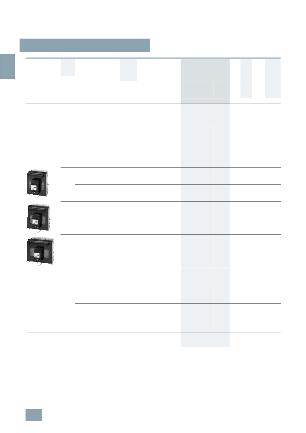
NP LV HRC fuse switch disconnectors
3/74
Siemens ET B1 · 10/2008
3
*
You can order this quantity or a multiple thereof.
1)
See LV HRC Fuse Links
.
2)
SIRIUS motor starter protectors: auxiliary switches, 2 NC also available on
request.
3)
The relevant 3NY1 106 cable lug covers must be used for 3NP50 60 with
flat terminals (see Accessories) for the purpose of protection against
accidental contact according to DIN VDE 0106-100
(
see page 3/76)
.
4)
According to DIN 46234 or 16 mm
2
... 95
mm
2
according to DIN 46235
(
use M10 cable lug if necessary).
5)
According to DIN 46234 or DIN 46235, with cable lug according to
DIN 46235: min. conductor cross-section 16 mm
2
(
use M12 cable lugs if
required).
6)
For accessories and further devices on busbar systems,
see Accessories
and Switchgear, SIVACON Distribution Boards and Cabinet Systems ->
Components for 8US, 8UC, 4NC distribution board systems -> 8US busbar
systems.
Rated
residual
current
Connection type
(
double-ended)
For LV
HRC fuse
links acc.
to DIN
43620
1)
Auxiliary switches
(
AS)
Degree of protection IP00,
without fuse links,
without isolating links,
with terminal screws
On
On
I
u
Connection For
conductor
cross-section
Switch
discon-
nectors
Motor
starter
protec-
tors
DT Order No.
Price
per PU
PG PU PS*/
P. unit
Weight
per PU
approx.
A
mm
2
Size
Unit(s) Unit(s) kg
Surface mounting and installation
Completely compartmentalized, with high speed closing feature
and fuse monitoring by SIRIUS motor starter protectors
2)
With plug-in connection of the auxiliary switch connecting cable
(
length approx. 1 m) to the motor starter protector
160
Flat
terminals
3)
2.5 ... 150
4)
00
a. 000 1 NO +
1
NC
1
NO +
1
NC
}
3
NP50 60-0EA86
103 1 1
2.484
1
NO +
1
NC
2
NO B
3
NP50 60-0EA26
103 1 1
2.550
Clamp
terminals
1
conductor
2.5 ... 50
00
a. 000 1 NO +
1
NC
1
NO +
1
NC
B
3
NP50 60-0EB86
103 1 1
2.616
2
conductors
1
×
2.5 ... 50
1
×
2.5 ... 35
1
NO +
1
NC
2
NO B
3
NP50 60-0EB26
103 1 1
2.650
250
Flat
terminals
6 ... 150
5)
1
and 0 1 NO +
1
NC
1
NO +
1
NC
}
3
NP52 60-0EA86
103 1 1
6.014
1
NO +
1
NC
2
NO B
3
NP52 60-0EA26
103 1 1
6.867
Clamp
terminals
35 ... 120 1
and 0 1 NO +
1
NC
1
NO +
1
NC
B
3
NP52 60-0EB86
103 1 1
7.095
1
NO +
1
NC
2
NO B
3
NP52 60-0EB26
103 1 1
6.659
400
Flat
terminals
6 ... 240
5)
2
and 1 1 NO +
1
NC
1
NO +
1
NC
}
3
NP53 60-0EA86
103 1 1
7.083
1
NO +
1
NC
2
NO B
3
NP53 60-0EA26
103 1 1
5.410
630
Flat
terminals
6 ... 2
×
240
5)
3
and 2 1 NO +
1
NC
1
NO +
1
NC
}
3
NP54 60-0EA86
103 1 1
8.462
1
NO +
1
NC
2
NO B
3
NP54 60-0EA26
103 1 1
9.233
For 40 mm busbar system
Completely compartmentalized, with high speed closing and
fuse monitoring by SIRIUS motor starter protectors
2) 6)
Busbar width: 12 mm and 5 mm or 10 mm thickness
160
Flat
terminals
2.5 ... 150
4)
00
a. 000 1 NO +
1
NC
1
NO +
1
NC
A
3
NP50 65-1EF86
103 1 1
2.908
Connection,
bottom
1
NO +
1
NC
2
NO B
3
NP50 65-1EF26
103 1 1
2.950
Clamp
terminals
1-
wire
00
a. 000 1 NO +
1
NC
1
NO +
1
NC
B
3
NP50 65-1EG86
103 1 1
3.020
2.5 ... 50
2
conductors
1
×
2.5 ... 50
1
×
2.5 ... 35
with bottom connection
1
NO +
1
NC
2
NO C
3
NP50 65-1EG26
103 1 1
2.973
For 60 mm busbar system
Use switch version "Surface mounting and installation" and
busbar adapter,
see page 3/82
.
© Siemens AG 2008