


 225 / 582

BETA Protecting
Low-Voltage Fuse Systems
3
NP LV HRC fuse switch disconnectors
3/75
Siemens ET B1 · 10/2008
3
*
You can order this quantity or a multiple thereof.
1)
See LV HRC Fuse Links.
2)
The relevant 3NY1 106 cable lug covers must be used for 3NP50 60 with
flat terminals (see Accessories) for the purpose of protection against
accidental contact according to DIN VDE 0106-100
(
see page 3/76)
.
3)
According to DIN 46234 or 16 mm
2
... 95
mm
2
according to DIN 46235
(
use M10 cable lug if necessary).
4)
According to DIN 46234 or DIN 46235; with cable lug according to
DIN 46235: Conductor cross-section min 16 mm
2
(
use M12 cable lugs if
required).
Rated
residual
current
Connection type
(
double-ended)
For LV HRC
fuse links
acc. to
DIN 43620
1)
Auxiliary switches
Degree of protection IP00,
without fuse links,
without isolating links,
with terminal screws
On
On
I
u
Connection For
conductor
cross-section
Switch
discon-
nectors
Fuse
monitor-
ing
DT Order No.
Price
per PU
PG PU PS*/
P. unit
Weight
per PU
approx.
A
mm
2
Size
Version Version
Unit(s) Unit(s) kg
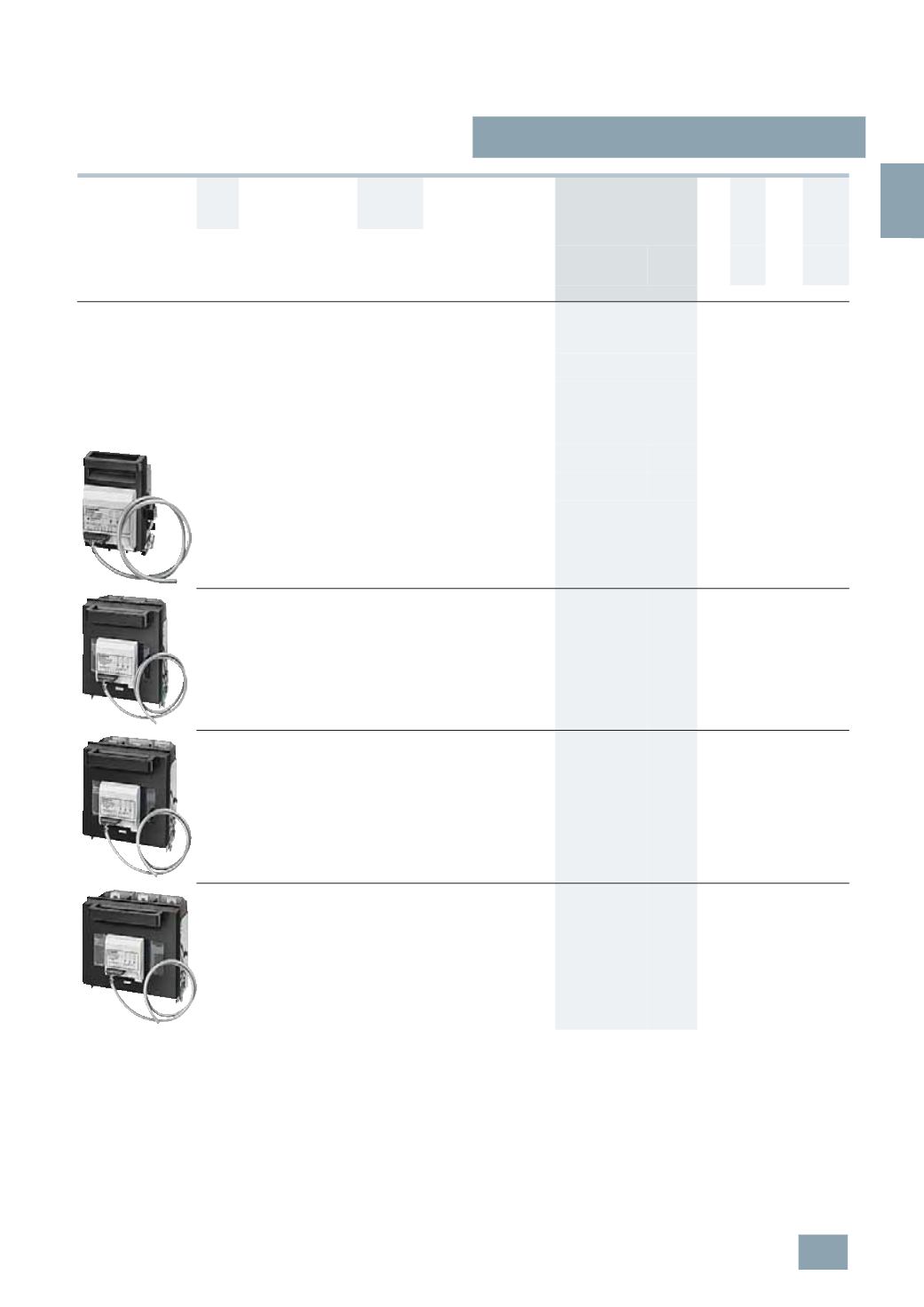
Surface mounting and Installation
Completely compartmentalized, with high speed closing feature
With electronic fuse monitoring EF (self-powered),
open-circuit principle
For rated operational voltages U
e
of 400 V to 500 V AC,
infeed must be from the top!
With plug-in connection of auxiliary switch connecting cable
(
length approx. 1 m) for fuse monitoring,
status display: green LED, illuminated,
fault indication: green LED, flashing,
fuse failure: red LED (display per phase)
160
Flat
terminals
2)
2.5 ...120
3)
00
a. 000 1 NO +
1
NC
2
NO +
1
NC
B
3
NP50 60-0HA13
103 1 1
2.375
Clamp
terminals
1-
wire:
2.5 ... 50
00
a. 000 1 NO +
1
NC
2
NO +
1
NC
B
3
NP50 60-0HB13
103 1 1
2.500
2-
wire:
1
×
2.5 ... 50
1
×
2.5 ... 35
250
Flat
terminals
6 ... 150
4)
1
and 0 1 NO +
1
NC
2
NO +
1
NC
B
3
NP52 60-0HA13
103 1 1
5.865
400
Flat
terminals
6 ... 240
4)
2
and 1 1 NO +
1
NC
2
NO +
1
NC
B
3
NP53 60-0HA13
103 1 1
6.951
630
Flat
terminals
6 ... 240
4)
3
and 2 1 NO +
1
NC
2
NO +
1
NC
B
3
NP54 60-0HA13
103 1 1
8.513
© Siemens AG 2008