




 221 / 543

Circuit-breakers, switch-disconnectors
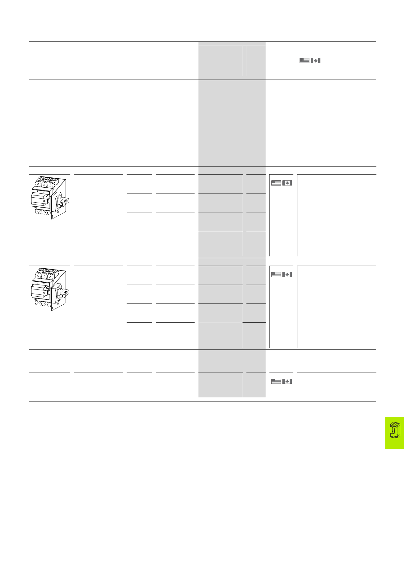
Main switch assembly kit
2010 CA08103002Z-EN
www.eaton.com17/125
Main switch assembly kit
Model
For use with
Part no.
Article no. when
ordered separately
Price
See
price
list
Std. pack
Information relevant for export to
North America
Main switch assembly kit for side wall installation with mounting
bracket.
For direct mounting of circuit-breaker and handle in the side wall of the control
cabinet
Equipment supplied:
• Door coupling rotary handle
• Mounting bracket
• Special short extension shaft
• External warning plate/designation label in German/English
• Black and yellow flash
For enhanced protection against direct contact on the incomer side,
IP2X protection against contact with a finger can be ordered→Page 17/84
Other external warning plates/designation labels can be clipped on.
Degree of protection IP66/UL/CSA type 4X, 12
Standard, black/grey
Lockable in 0 position,
with adequate
modification also in
I position. Minimum
clearance between
control panel side
walls and circuit-
breaker is defined by
mounting bracket.
Extension cannot be
used.
For
operation
on the left
NZM1(-4)
PN1(-4), N(S)1(-4)
NZM1-XSM-L
266663
1 off
Product Standards UL489;
CSA-C22.2
No. 5-09;
IEC60947,
CE marking
UL File No.
E140305
UL CCN
DIHS
CSA File No.
022086
CSA Class No.
1437-01
NA Certification
UL Listed,
CSA certified
Degree of Protection IEC: IP66,
UL/CSA
Type 4X, 12
For
operation
on the left
NZM2(-4)
PN2(-4), N(S)2(-4)
NZM2-XSM-L
266664
For
operation
on the right
NZM1(-4)
PN1(-4), N(S)1(-4)
NZM1-XSM-R
266665
For
operation
on the right
NZM2(-4)
PN2(-4), N(S)2(-4)
NZM2-XSM-R
266666
Red-yellow for emergency switching off
Lockable in 0 position
on handle. Minimum
clearance between
control panel side
walls and circuit-
breaker is defined by
mounting bracket.
Extension cannot be
used.
For
operation
on the left
NZM1(-4)
PN1(-4), N(S)1(-4)
NZM1-XSRM-L
266671
1 off
Product Standards UL489;
CSA-C22.2
No. 5-09;
IEC60947,
CE marking
UL File No.
E140305
UL CCN
DIHS
CSA File No.
022086
CSA Class No.
1437-01
NA Certification
UL Listed,
CSA certified
Degree of Protection IEC: IP66,
UL/CSA
Type 4X, 12
For
operation
on the left
NZM2(-4)
PN2(-4), N(S)2(-4)
NZM2-XSRM-L
266672
For
operation
on the right
NZM1(-4)
PN1(-4), N(S)1(-4)
NZM1-XSRM-R
266673
For
operation
on the right
NZM2(-4)
PN2(-4), N(S)2(-4)
NZM2-XSRM-R
266674
Additional plate
For fitting to the mounting bracket when using neutral conductor or
PE conductor terminals K25, K50, K95 or K150.
–
–
NZM1(-4),
PN1(-4), N(S)1(-4)
NZM2(-4),
N(S)2(-4)
NZM1/2-XZB
266676
1 off
UL/CSA certification not required
Notes
Additional terminal arrangement for side wall operator with mounting bracket.
→Engineering, Page 17/153
NZM...XS(R)M...
HPL17125EN