


 126 / 439

5/122
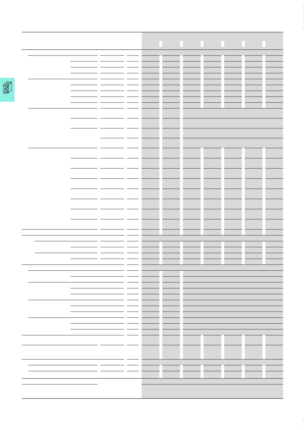
Contactors
Comfort devices and standard devices greater than 170 A
2010
CA08103002Z-EN
www.eaton.comMagnet systems
Voltage tolerance
1)
AC operated
Pick-up
x U
c
0.8 - 1.15 0.8 - 1.15
AC operated
Drop-out
x U
c
0.25 - 0.6 0.25 - 0.6
DC operated
Pick-up
x U
c
0.7 - 1.2
0.7 - 1.2
DC operated
Drop-out
x U
c
0.15 - 0.6 0.15 - 0.6
Power consumption of the
coil in a cold state and
1.0
x U
c
50/60
Hz
Pick-up
VA 210
210
–
–
–
–
–
50/60
Hz
Sealing
VA 2.6
2.6
–
–
–
–
–
5
0/60
Hz
Sealing
W 2.6
2.6
–
–
–
–
–
DC operated
Pick-up
W 180
180
–
–
–
–
–
DC operated
Sealing
W 2.1
2.1
–
–
–
–
–
Voltage tolerance
Comfort series
DILM…
Pick-up
x U
c
–
–
0.7
x U
c min
- 1.15
x U
c max
Standard range
DILM…-S
Pick-up
x U
c
–
–
0.85
x U
c min
- 1.1
x U
c max
Comfort series
DILM…
Drop-out
x U
c
–
–
0.2
x U
c min
- 0.6
x U
c min
Standard range
DILM…-S
Drop-out
x U
c
–
–
0.2
x U
c min
- 0.4
x U
c min
Power consumption of the
coil in a cold state and
1.0
x U
c
Comfort series
DILM…
Pick-up
VA –
–
380
2)
380
2)
450
2)
450
2)
450
2)
Comfort series
DILM…
Pick-up
W –
–
250
250
350
350
350
Comfort series
DILM…
Sealing
VA –
–
4.3
4.3
4.3
4.3
4.3
Comfort series
DILM…
Sealing
W –
–
3.3
3.3
3.3
3.3
3.3
Standardrange
DILM…-S
Pick-up
VA –
–
360
4)
360
4)
715
4)
715
4)
715
4)
Standardrange
DILM…-S
Pick-up
W –
–
325
625
645
645
645
Standardrange
DILM…-S
Sealing
VA –
–
4.3
4.3
4.3
4.3
4.3
Standardrange
DILM…-S
Sealing
W –
–
3.3
3.3
3.3
3.3
3.3
Duty factor
%
DF –
–
100
100
100
100
100
Changeover time at 100 % U
c
(
recommended values), main circuit
Comfort series
DILM…
Closing delay
ms
–
–
< 100
< 80
< 80
< 80
< 80
Opening delay
ms
–
–
< 110
< 110
< 110
< 110
< 110
Standard range
DILM…-S
Closing delay
ms
< 60
< 60
< 55
< 55
< 55
< 55
< 55
Opening delay
ms
< 40
< 40
< 40
< 40
< 50
< 50
< 50
Behavior in limit range and transition area, hold state
Voltage interruption (0 - 0.2 x U
c min
)
≦ 10 ms
–
–
Targeted bridging during this time
(0 - 0.2
x U
c min
)
> 10 ms
Drop-out of the contactor
Voltage drops
(0.2 - 0.6
x U
c min
)
≦ 12 ms
Targeted bridging during this time
(0.2 - 0.6
x U
c min
)
> 12 ms
Drop-out of the contactor
(0.6 - 0.7
x U
c min
)
Contactor remains switched on
Excess voltage
(1.15 - 1.3
x U
c max
)
Contactor remains switched on
(
> 1.3 x U
c max
)
≦ 3 s
Contactor remains switched on
(
> 1.3 x U
c max
)
> 3 s
Drop-out of the contactor
Pick-up phase
(0 - 0.7
x U
c min
)
Contactor does not switch on
(0.7
x U
c min
- 1.15
x U
c max
)
Contactor switches on safely
(
> 1.15 x U
c max
)
Contactor switches on safely
Permissible transitional contact resistance
(
of external control unit when A11 is actuated)
mΩ
–
–
≦ 500
≦ 500
≦ 500
≦ 500
–
Permissible residual current ( when A11 is
actuated from the electronic system in the event
of a 0 signal)
mA –
–
≦ 1
≦ 1
≦ 1
≦ 1
–
PLC signal level (A3 - A4) to IEC/EN 61131-2 (part no. 2)
High
V
15
15
15
15
15
15
–
Low
V
5
5
5
5
5
5
–
Electromagnetic compatibility (EMC)
Electromagnetic compatibility
This product is designed for operation in industrial environments (environment 2).
The use in residential environments (environment 1) could cause electrical interference so
that addition suppression must be planned.
Notes
1)
U
c
min, U
c
max,
2)
Control transformer with u
k
≦ 0.6
3)
Control transformer with u
k
≦ 0.7
4)
u
k
≦ 10 %
Contactors
DILM185A DILM225A DILM250 DILM300A DILM400 DILM500 DILM570
DILM185...DILM1600, DILH