


 112 / 439

5/108
Contactors
Basic devices up to 170 A
2010
CA08103002Z-EN
www.eaton.comBasicdevicesup to 170A
DILM7
DILM9
DILM12
DILM15
DILM17
DILM25
General
Standards
IEC/EN 60947, VDE 0660, UL, CSA
Lifespan, mechanical
AC operated
c (contacts)
x 10
6
10
10
10
10
10
10
DC operated
c (contacts)
x 10
6
10
10
10
10
10
10
Operating frequency, mechanical
Mechanical, AC operated
Operations/h
9000
9000
9000
5000
5000
5000
DC operated
Operations/h
9000
9000
9000
5000
5000
5000
Maximum operating frequency
Electrical (Contactor without overload relay)
→ Characteristic curves Page 5/78
Climatic proofing
Damp heat, constant, to IEC 60068-2-78
Damp heat, cyclic, to IEC 60068-2-30
Ambient temperature
Open
°C
-25…60
-25…60
-25…60
-25…60
-25…60
-25…60
Enclosed
°C
-25…40
-25…40
-25…40
-25…40
-25…40
-25…40
Storage
°C
-40 - 80
-40 - 80
-40 - 80
-40 - 80
-40 - 80
-40 - 80
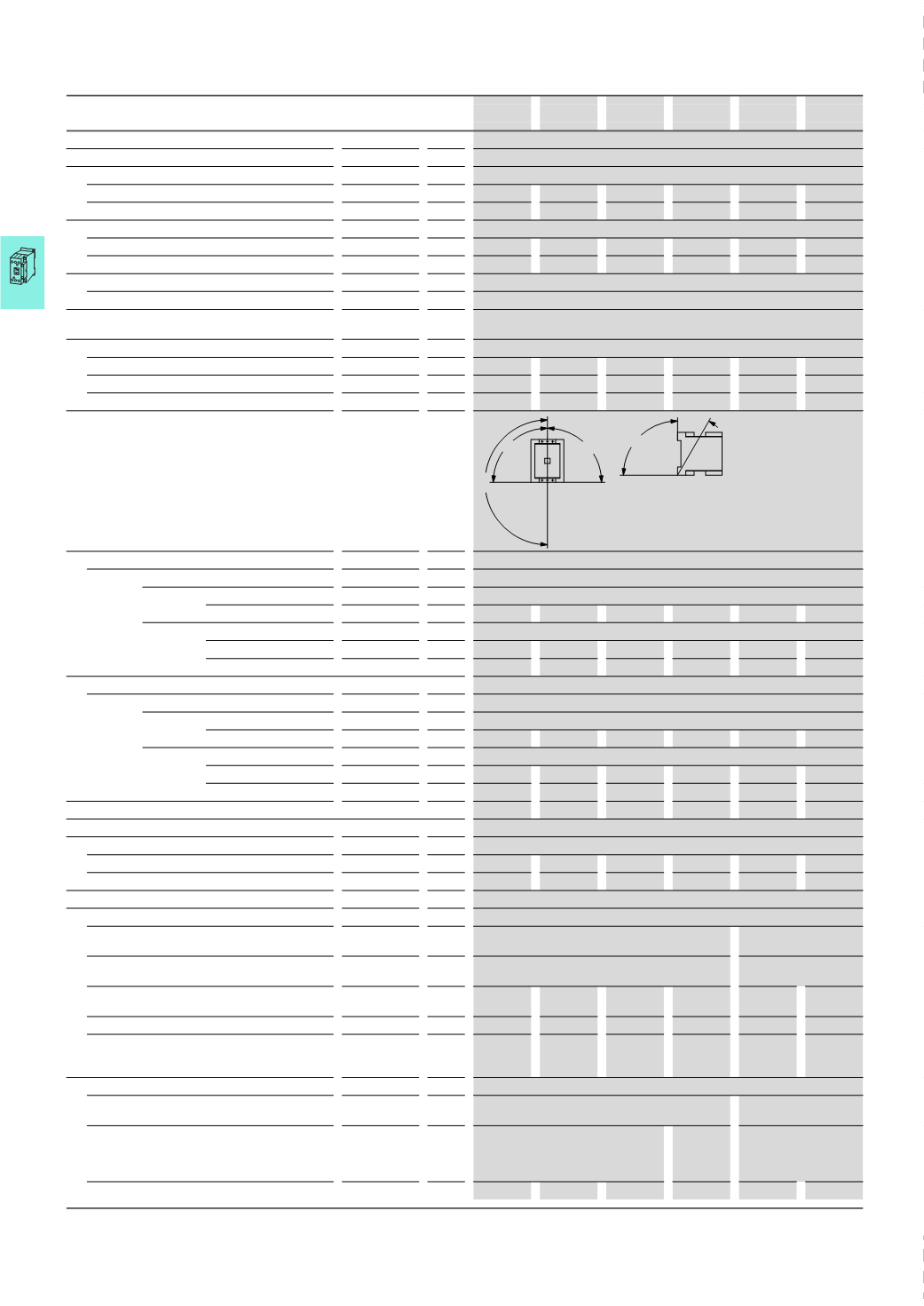
Mounting position AC- and DC operated
Mechanical shock resistance (IEC/EN 60068-2-27)
Half-sinusoidal shock 10 ms
Main contacts
N/O
g
10
10
10
10
10
10
Auxiliary contacts
N/O
g
7
7
7
7
7
7
NC
g
5
5
5
5
5
5
Mechanical shock resistance (IEC/EN 60068-2-27) with table mounting
Half-sinusoidal shock 10 ms
Main contacts
N/O
g
5.7
5.7
5.7
5.7
6.9
6.9
Auxiliary contacts
N/O
g
3.4
3.4
3.4
3.4
5.3
5.3
NC
g
3.4
3.4
3.4
3.4
3.5
3.5
Protection type
IP20
IP20
IP20
IP20
IP00
IP00
Protection against direct contact when actuated from front (EN 50274)
Finger- and back-of-hand proof
Weight
AC operated
kg
0.23
0.23
0.23
0.23
0.42
0.42
DC operated
kg
0.28
0.28
0.28
0.28
0.48
0.48
Terminal type, screw connection
Terminal capacity of main cable
Solid
mm
2
1
x (0.75 - 4)
2
x (0.75 - 2.5)
1
x (0.75 - 16)
2
x (0.75 - 10)
Flexible with ferrule
mm
2
1
x (0.75 - 2.5)
2
x (0.75 - 2.5)
1)
1
x (0.75 - 16)
2
x (0.75 - 10)
Stranded
mm
2
–
–
–
–
1
x 16
1
x 16
Solid or stranded
AWG 18 - 10
18 - 10
18 - 10
18 - 10
18 - 6
18 - 6
Flat conductor
Number of
layers x width x
thickness
mm –
–
–
–
–
–
Terminal capacity of control circuit cable
Solid
mm
2
1
x (0.75 - 4)
2
x (0.75 - 2.5)
1
x (0.75 - 4)
2
x (0.75 - 4)
Flexible with ferrule
mm
2
1
x (0.75 - 2.5)
2
x (0.75 - 2.5)
1
x
(0.75 - 2.5)
2
x
(0.75 - 2.5)
1
x (0.75 - 2.5)
2
x (0.75 - 2.5)
Solid or stranded
AWG 18 - 10
18 - 10
18 - 10
18 - 10
18 - 14
18 - 14
Notes
1)
Also without ferrule.
180
°
90
°
90
°
90
˚
30
˚
DILM7 ... DILM170