


 118 / 439

5/114
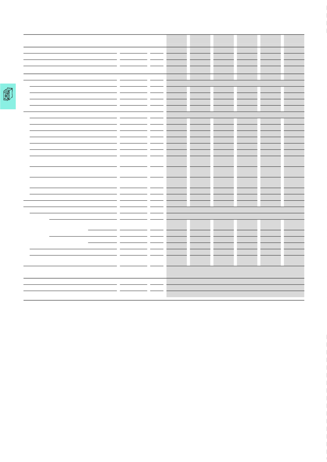
Contactors
Basic devices up to 170 A
2010
CA08103002Z-EN
www.eaton.comDILM7
DILM9
DILM12
DILM15
DILM17
DILM25
Current heat loss (3 pole)
Current heat loss at I
th
W 3
3
3
3
7.3
9.6
Current heat loss at I
e
to AC-3/400 V
W 0.37
0.6
1.1
1.8
1.9
3.8
Impedance per pole
mΩ
2.5
2.5
2.5
2.5
2
2
Magnet systems
Voltage tolerance
AC operated
Pick-up
x U
c
0.8 - 1.1
0.8 - 1.1
0.8 - 1.1
0.8 - 1.1
0.8 - 1.1
0.8 - 1.1
AC operated
Drop-out
x U
c
0.3 - 0.6
0.3 - 0.6
0.3 - 0.6
0.3 - 0.6
0.3 - 0.6
0.3 - 0.6
DC operated
3)
Pick-up
x U
c
0.8 - 1.1
0.8 - 1.1
1)
0.8 - 1.1
1)
0.8 - 1.1
1)
0.7 - 1.2
2)
0.7 - 1.2
2)
DC operated
3)
Drop-out
x U
c
0.15 - 0.6
0.15 - 0.6
0.15 - 0.6
0.15 - 0.6
0.15 - 0.6
0.15 - 0.6
Power consumption of the coil in a cold state and 1.0 x U
c
50
Hz
Pick-up
VA 24
24
24
24
52
52
50
Hz
Sealing
VA 3.4
3.4
3.4
3.4
7.1
7.1
50
Hz
Sealing
W 1.2
1.2
1.2
1.2
2.1
2.1
60
Hz
Pick-up
VA 30
30
30
30
67
67
60
Hz
Sealing
VA 4.4
4.4
4.4
4.4
8.7
8.7
60
Hz
Sealing
W 1.4
1.4
1.4
1.4
2.6
2.6
50/60
Hz
Pick-up
VA 27
25
27
25
27
25
27
25
62
58
62
58
50/60
Hz
Sealing
VA 4.2
3.3
4.2
3.3
4.2
3.3
4.2
3.3
9.1
6.5
9.1
6.5
50/60
Hz
Sealing
W 1.4
1.2
1.4
1.2
1.4
1.2
1.4
1.2
2.5
2
2.5
2
DC operated
Pick-up
W 3
3
4.5
4.5
12
12
DC operated
Sealing
W 3
3
4.5
4.5
0.5
0.5
Duty factor
%
DF 100
100
100
100
100
100
Changeover times at 100 % U
c
(
recommended values)
Main contacts
AC operated
Closing delay
ms
15…21
15…21
15…21
15…21
16…22
16…22
Opening delay
ms
9…18
9…18
9…18
9…18
8…14
8…14
DC operated
Closing delay
ms
31
31
31
31
47
47
Opening delay
ms
12
12
12
12
30
30
Arcing time
ms
10
10
10
10
10
10
Permissible residual current when A1 - A2 are
actuated from the electronic system (with 0 signal)
mA –
–
–
–
–
–
Lifespan, mechanical; Coil 50/60 Hz
At 50 Hz
Mechanical lifespan at 50 Hz approx. 30% lower than under →Technical data
general
Electromagnetic compatibility (EMC)
Emitted interference
To EN 60947-1
Interference immunity
To EN 60947-1
Notes
1)
At 24 V DC: 0.7 – 1.3 without auxiliary contact module and at ambient temperature + 40 °C
2)
RDC 24 (Umin 24 V DC/Umax 27 V DC)
RDC 60 (Umin 48 V DC/Umax 60 V DC)
RDC 130 (Umin 110 V DC/Umax 130 V DC)
RDC 240 (Umin 200 V DC/Umax 240 V DC)
Example: Uc = 0.7 x Umin - 1.2 x Umax / Uc = 0.7 x 24 V - 1.2 x 27 V DC
3)
At least: smoothed two-phase bridge rectifier or three-phase rectifier
DILM7 ... DILM170