


 258 / 300

TSC-0912 - 09.10.12
Furse, Wilford Road, Nottingham, NG2 1EB • Tel: +44 (0)115 964 3700 • Email:
enquiry@furse.com• Web:
www.furse.comESP RF Series
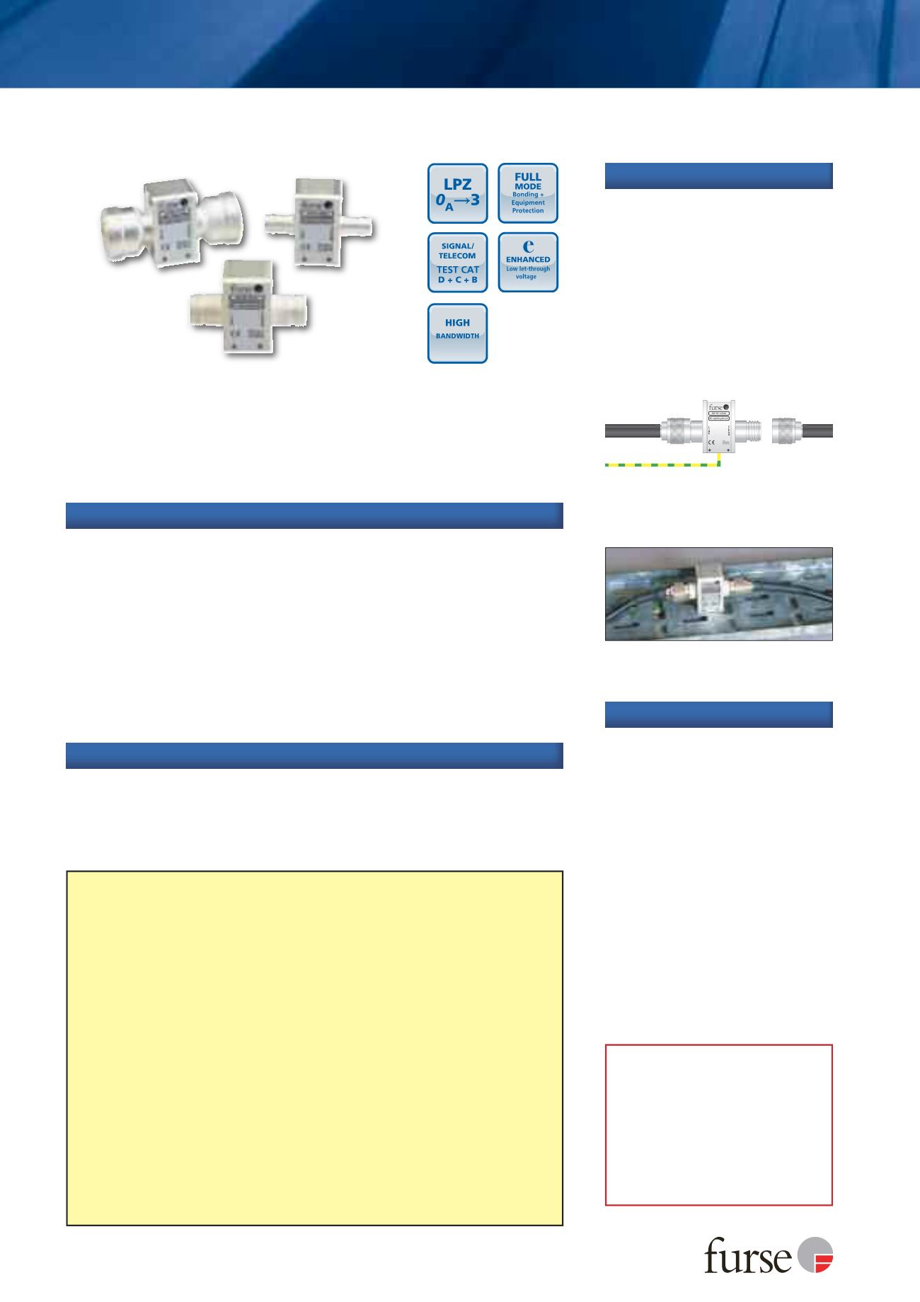
ESP RF 111121 on a coaxial cable running
between an antenna and an RF receiver
Part numbering system
Furse RF protectors have six digit part codes, prefixed with ESP RF. The selected
digits define the exact specification of the required protector, e.g.
ESP RF
AABCDE
Connector type - ESP RF
AA
xxxx
The first 2 digits refer to the connector type:
11
- N type female
AA
- 7/16 DIN type female
44
- BNC female
Line impedance - ESP RF xx
B
xxx
3rd digit refers to the line impedance. Currently
only one option:
1
- 50
Ω
transmission line.
Gas Discharge Tube (GDT) selection - ESP RF xxx
C
xx
Select the 4th digit from the
table at the bottom of page 259.
Selection of the correct GDT is critical in the effectiveness of using these protectors.
For the correct GDT, take the maximum RF power or voltage of the system and
select a GDT with a voltage/power handling greater than the system.
Important note:
When using the peak RF voltage to select the GDT, if the system is
a multi-carrier system the (in phase) peak RF voltage can be calculated as the total
of all the single carrier peak voltages on the transmission line.
Protector rating - ESP RF xxxx
D
x
5th digit specifies the protector rating.
1
- Higher specification (see pages 260-261)
2
- Standard specification (see pages 258-259)
Case plating - ESP RF xxxxx
E
6th digit specifies the case plating.
1
- White bronze
2
- Silver
ESP RF 111A21 with N female connectors
installed in series
DIRTY
CLEAN
From line
To
equipment
Earth
Technical note
These protectors are based on a
continuous transmission line
with a GDT connected between
this line and screen/earth, and
are suited for applications
where DC is required to pass to
the equipment.
Restricts let-through voltage below damage levels of interface circuitry
Very low attenuation and near unity VSWR over a wide range of
frequencies ensure the protectors do not impair system performance
Wide bandwidth means a single product is suitable for a range of
applications, including the transmission of DC power
Easily mounted and earthed via fixtures on the base of the unit
Available with N, 7/16 DIN and BNC connectors
Additional mounting plates give increased flexibility
Robust white bronze plated aluminium housing (silver plate option)
Features and benefits
Combined Category D, C, B tested protector (to BS EN 61643) suitable
for RF systems using coaxial cables at frequencies between DC and
2.7 GHz and where DC power is present. Suitable for RF systems
with power up to 2.3 kW. For use at boundaries up to LPZ
0
A
to
protect against flashover (typically the service entrance location)
through to LPZ 3 to protect sensitive electronic equipment.
ESP RF BK1
Straight mounting plates
ESP RF BK2
90° angled mounting plates
ESP RF BK3
Bulkhead through mounting plate
(single)
ESP RF BK4
Bulkhead through mounting plate
(for 4 products)
ESP RF GDT-x
Replacement gas discharge tubes
(Where x is the correct GDT part
code digit for your system.
See GDT selection, page 259).
Accessories
In a building, connect in series
with the coaxial cable near where
it enters or leaves the structure, or
close to the equipment being
protected. On a mast, connect in
series with the coaxial cable near
the antenna/dish being protected.
Install in a radio communications
room, an existing cabinet or a
suitable enclosure.
Installation
Use on coaxial cables to protect RF transmitter and receiver systems, including
electronics located at the antenna or dish. Typical examples include cell sites,
military communications, satellite earth stations and pager systems. They can
be used in applications where DC power is required to pass to the equipment.
Application