


 257 / 300

TSC-0912 - 09.10.12
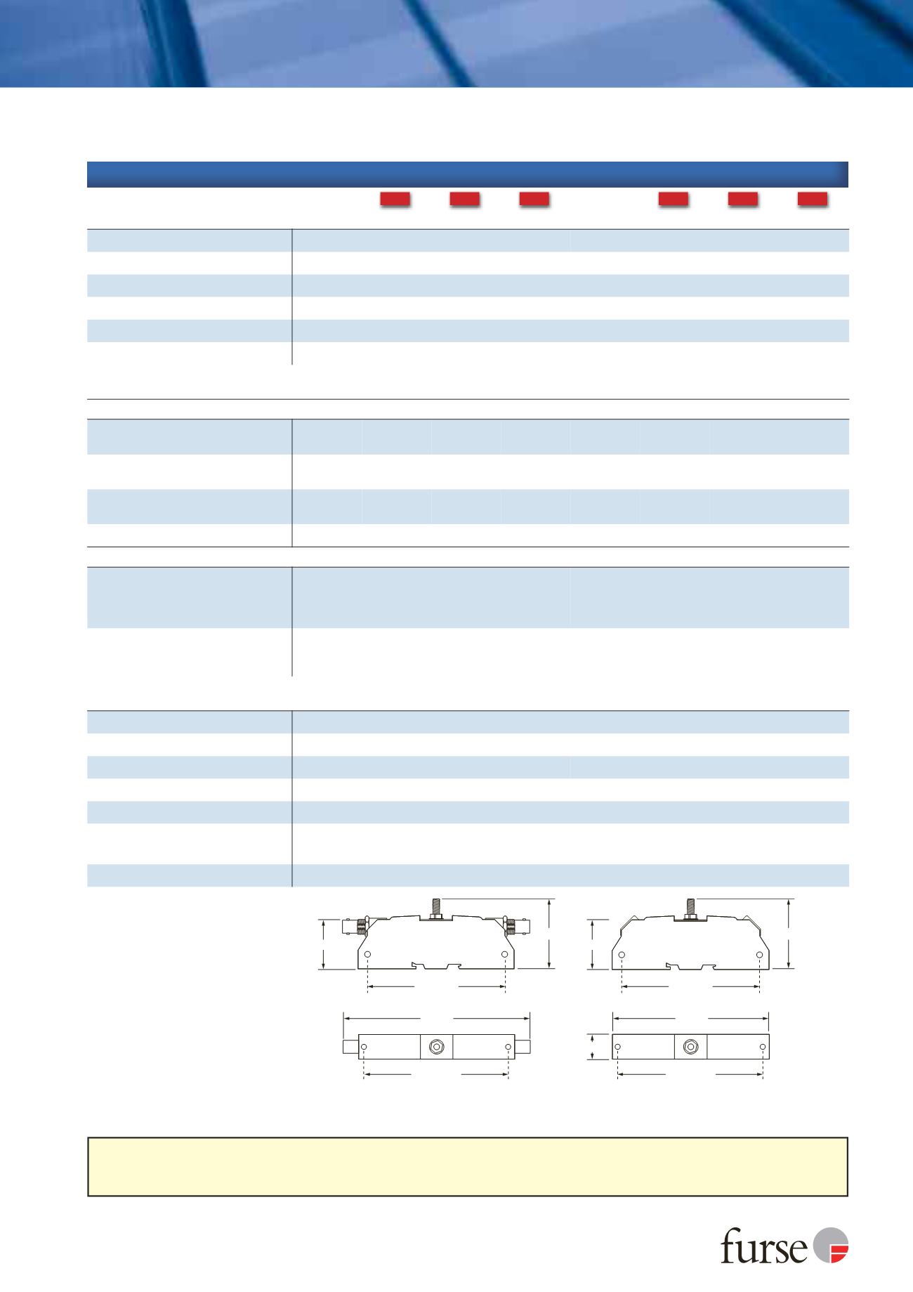
144 mm
38 mm
54 mm
105 mm
M4 clearance
109 mm
M4 clearance
NEW NEW NEW
NEW NEW NEW
Furse, Wilford Road, Nottingham, NG2 1EB • Tel: +44 (0)115 964 3700 • Email:
enquiry@furse.com• Web:
www.furse.comESP CCTV Series
Camera telemetry or control lines should be protected with a suitable Lightning Barrier from the ESP D or E Series. Protectors for the power supply
to individual cameras (e.g. ESP 240-16A) and the mains supply to the control room (e.g. ESP 240 D1) are available. For coaxial RF (ESP RF Series)
cable protectors and CATV systems (ESP CATV/F) are also available.
Technical specification
1
Nominal voltage (DC or AC peak) measured at
<10 µA leakage.
2
Maximum working voltage (DC or AC peak) measured
at 5 mA leakage.
3
Capacitance < 30 pF.
4
The maximum transient voltage let-through of the
protector throughout the test (±10%), line to line &
line to earth. Screen to earth let-through voltage will
be up to 600 V (with 5 kV 10/700 test), when
protector is configured for use with non-earthed or
isolated screen systems. Response time < 10 ns.
5
Test to IEC 61000-4-5:2006, ITU-T (formerly CCITT)
K.20, K.21 and K.45,Telcordia GR-1089-CORE,
Issue 2:2002, ANSI TIA/EIA/IS-968-A:2002 (formerly
FCC Part 68).
6
The installation and connectors external to the
protector may limit the capability of the protector.
120 mm
38 mm
19 mm
54 mm
105 mm
M4 clearance
109 mm
M4 clearance
Electrical specification
ESP CCTV/B ESP CCTV/B-15V ESP CCTV/B-30V ESP CCTV/B-50V ESP CCTV/T ESP CCTV/T-15V ESP CCTV/T-30V ESP CCTV/T-50V
Nominal voltage
1
(peak-peak)
1 V
2 V
Maximum working voltage
U
c
2
(peak)
7.79 V
16.7 V
36.7 V
56.7 V
7.79 V
16.7 V
36.7 V
56.7 V
Current rating
(signal)
300 mA
In-line resistance
(±10%)
1
Ω
inserted in coax inner
1
Ω
per line
Bandwidth
(-3 dB 75
Ω
system)
3
> 100 MHz
Voltage standing wave ratio
< 1.2:1
Transient specification
ESP CCTV/B ESP CCTV/B-15V ESP CCTV/B-30V ESP CCTV/B-50V ESP CCTV/T ESP CCTV/T-15V ESP CCTV/T-30V ESP CCTV/T-50V
Let-through voltage
(all conductors)
4
U
p
C2 test 4 kV 1.2/50 µs, 2 kA 8/20 µs to
BS EN/EN/IEC 61643-21
39.5 V
55.0 V
78.0 V
105.0 V
39.5 V
55.0 V
78.0 V
105.0 V
C1 test 1 kV, 1.2/50 µs, 0.5 kA 8/20 µs to
BS EN/EN/IEC 61643-21
26.0 V
42.0 V
66.5 V
93.5 V
26.0 V
42.0 V
66.5 V
93.5 V
B2 test 4 kV 10/700 µs to
BS EN/EN/IEC 61643-21
16.0 V
27.2 V
47.5 V
73.6 V
16.0 V
27.2 V
47.5 V
73.6 V
5 kV, 10/700 µs
5
17.0 V
28.2 V
49.5 V
76.2 V
17.0 V
28.2 V
49.5 V
76.2 V
Maximum surge current
6
D1 test 10/350 µs to
BS EN/EN/IEC 61643-21
- per signal wire
- per pair
2.5 kA
-
2.5 kA
5 kA
8/20 µs to ITU (formerly CCITT),
- per signal wire
- per pair
10 kA
-
10 kA
20 kA
Electrical specification
ESP CCTV/B variants
ESP CCTV/T variants
Temperature range
-40 to +80 ºC
Connection type
Coaxial BNC female
Screw terminal
Conductor size
(stranded)
Not applicable
2.5 mm
2
Earth connection
M6 stud
Casing material
Conductive ABS UL94 V-0
Weight -
unit
0.08 kg
Weight
-
packaged (per 10)
0.9 kg
Dimensions
CCTV/B
CCTV/T