


 253 / 300

TSC-0912 - 09.10.12
ESP SSI Series
Electrical specification
ESP SSI/M ESP SSI/B
Maximum signal voltage
1
7 V
Maximum common mode
stand-off voltage
90 Vrms
Current rating
100 mA
In-line resistance
(per line, ±10%)
4.5
Ω
Leakage
(Line to line impedance)
(Line to earth impedance)
> 1 M
Ω
> 10 k
Ω
Differential bandwidth
(50
Ω
system)
10 MHz
ESP SSI/B
This is a modified 11 pin ‘relay type’ socket containing a 100
Ω
±5%
wire-wound 2.5 W resistor connected between terminals 8 and 9.
Internal links between terminals 2 & 3, 9 & 10, and 1 & 11.
Transient specification
ESP SSI/M ESP SSI/B
Transverse (Differential)
‘let-through’ voltage
2
U
p
15 V
Common mode ‘let-through’
voltage
3
U
p
250 V
Mechanical specification
ESP SSI/M ESP SSI/B
Temperature range
-40 to +80 ºC
Connection type
-
Screw terminal
Fixing connection
- Flat mount
-
Two M4 fixing
holes with
35 mm centres
- Top Hat Din rail mount (ESP SSI/B)
-
An integral clip
- G Din rail mount (ESP SSI/B/G)
-
Two mounting
clips with screws
Max load
-
10 A, 250 V
Casing material
ABS UL94 V-0
Weight -
unit
0.065 kg
0.075 kg
Weight
-
packaged (per 50)
3.25 kg
3.9 kg
Dimensions
ESP SSI/120AC ESP SSI/140AC
Nominal voltage - Phase - Neutral
U
o
(RMS)
120 V
140 V
Maximum working voltage -
Phase - Neutral
U
c
(RMS)
150 V
165 V
Working voltage
(RMS)
90-150 V
90-165 V
Frequency range
47-63 Hz
Current rating
(supply) -
see installation instructions
100 A
Leakage current
(to earth)
< 60 µA
Indicator circuit current
< 10 mA
Volt free contact
4
- current rating
- nominal voltage (RMS)
Screw terminal
200 mA
250 V
ESP SSI/120AC ESP SSI/140AC
Let-through voltage (all conductors)
Type 2 (BS EN/EN), Class II (IEC)
Nominal discharge current 8/20 µs
(per mode)
I
n
5 kA
Let-through voltage
U
p
at
I
n
5
460 V
540 V
Maximum discharge current
I
max
(per mode)
6
20 kA
Type 3 (BS EN/EN), Class III (IEC
)
Let-through voltage at
U
oc
of 6 kV 1.2/50 µs
and
I
sc
of 3 kA 8/20 µs (per mode)
7
400 V
500 V
ESP SSI/120AC ESP SSI/140AC
Temperature range
-40 to +80 ºC
Connection type
Screw terminal
Conductor size
(stranded)
16 mm
2
Earth connection
Screw terminal
Volt free contact
Connect via screw terminal with
conductor up to 2.5 mm
2
(stranded)
Case material
Steel
Weight -
unit
0.5 kg
-
packaged
0.6 kg
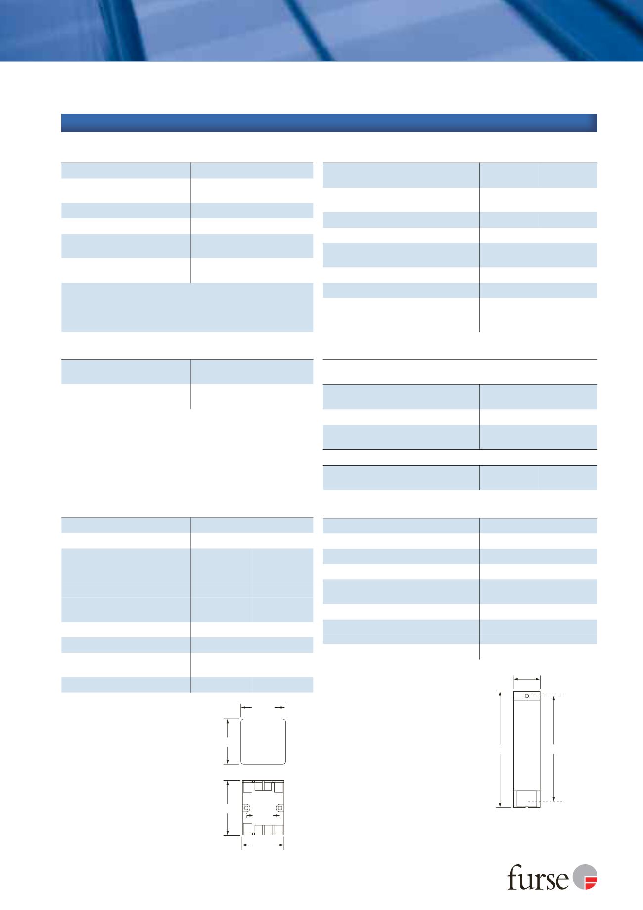
Dimensions
40 mm
ESP SSI
120/AC
or
ESP SSI
140/AC
176 mm
165 mm
5
Depth: 70 mm
M5 clearance
50 mm
43 mm
ESP SSI/M
50 mm
56 mm
Depth: 44 mm
Depth: 69 mm
35 mm
ESP SSI/B
Technical specification
Furse, Wilford Road, Nottingham, NG2 1EB • Tel: +44 (0)115 964 3700 • Email:
enquiry@furse.com• Web:
www.furse.com1
Maximum signal voltage (DC or AC peak) measured
at 200 µA.
2
‘Let-through’ voltage is the maximum transient
voltage ‘let-through’ to the equipment to be
protected. C2 test (to BS EN/EN/IEC 61643-21)
2 kV 1.2/50 µs. 1 kA 8/20 µs. ‘Let-through’ voltage
(±10%).
3
‘Let-through’ voltage is the maximum transient
voltage ‘let-through’ to the equipment to be
protected. C2 test (to BS EN/EN/IEC 61643-21)
4 kV 1.2/50 µs. 2 kA 8/20 µs. ‘Let-through’ voltage
(±20%).
4
Minimum permissible load is 5 V DC, 10 mA to ensure
reliable contact operation.
5
The maximum transient voltage let-through of the
protector throughout the test (±5%), per mode.
6
The electrical system, external to the unit, may
constrain the actual current rating achieved in a
particular installation.
7
Combination wave test within IEEE C62.41-2002
Location Cats C1 & B3, SS CP 33:1996 App. F, AS
1768-1991 App. B, Cat B, UL1449 mains wire-in.