


 248 / 300

TSC-0912 - 09.10.12
Furse, Wilford Road, Nottingham, NG2 1EB • Tel: +44 (0)115 964 3700 • Email:
enquiry@furse.com• Web:
www.furse.comESP WT Series
NEW
Enhanced protection (to BS EN 62305) offering low let-through voltage
further minimizing the risk of flashover creating dangerous sparking or
electric shock
Repeated protection in lightning intense environments
The varistor based design eliminates the high follow current (
I
f
)
associated with spark gap based surge protection
Indicator shows when the protector requires replacement
Remote signal contact can indicate the protector’s status through
interfacing with a building management system
Features and benefits
Combined Type 1 and 2 tested protector (to BS EN 61643) for use on
the main distribution board within wind turbines, for equipotential
bonding. For use at boundaries up to LPZ
0
A
to protect against
flashover (typically the main distribution board location) through to
LPZ 2 to protect electrical equipment from damage.
Connecting and earthing bars
ESP CE7
Use with 3 of ESP 690/12.5/WT for
TN-C supplies
ESP CE9
Use with 3 of ESP 690/25/WT for
TN-C supplies
ESP CE10
Use with 4 of ESP 690/12.5/WT for
TN-S supplies
ESP CE13
Use with 4 of ESP 690/25/WT for
TN-S supplies
For suitable enclosures for the
ESP WT series, please contact us.
Accessories
Protector should be installed in
the main distribution board with
connecting leads of minimal
length. The protector should
be fused and is suitable for
attachment to a 35 mm top hat
DIN rail.
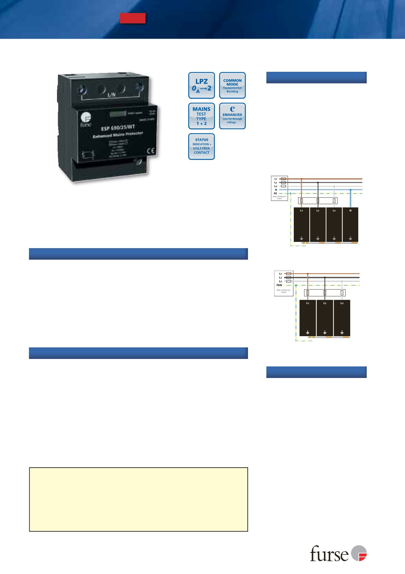
The diagrams below illustrate
how to wire the appropriate
ESP protector according to your
chosen electrical system.
Installation
Use on 690 V three phase mains power supplies and power distribution
boards for protection against partial direct and indirect lightning strikes.
The services (typically 3 phase 400 V mains, UPS, data, signal and telecom
lines) to the cabinet within the wind turbine nacelle will require
additional protection.
For a 3 phase TN-S supply, install 4 ESP WT units together with ESP CE10
or ESP CE13 connecting and earthing bar (see installation)
For a 3 phase TN-C supply, install 3 ESP WT units together with ESP CE7
or ESP CE9 connecting and earthing bar (see installation)
Application
TN-S earthing system (ESP WT x 4) with
ESP CE10 or ESP CE13 earthing bars
TN-C earthing system (ESP WT x 3) with
ESP CE7 or ESP CE9 earthing bars
IMPORTANT
The primary purpose of lightning current or equipotential bonding mains Type 1 Surge
Protective Devices (SPDs) is to prevent dangerous sparking caused by flashover to protect
against the loss of human life. In order to protect electronic equipment and ensure the
continual operation of systems, transient overvoltage mains Type 2 and 3 SPDs such as the
ESP M1 Series or ESP D1 Series are further required, typically installed at downstream sub-
distribution boards feeding sensitive equipment. BS EN/IEC 62305 refers to the correct
application of mains Type 1, 2 and 3 SPDs as a coordinated set.
For further information, please refer to the Furse Guide to BS EN 62305 Protection
against Lightning.