


 245 / 300

TSC-0912 - 09.10.12
Location
LPZ
SPD required
Generator
(690 V)
LPZ 0 to LPZ 1
ESP WT Series protector
See pages 248-249
Frequency converter
(690 V)
LPZ 0 to LPZ 2
ESP WT Series protector
See pages 248-249
Transformer
(690 V)
LPZ 0 to LPZ 1*
ESP WT Series protector
See pages 248-249
Control system
(230 V)
LPZ 0 to LPZ 1
ESP 240 D1 or ESP 240 M1
See pages 186-189, 192-193
Aviation warning
light (230 V)
LPZ 0 to LPZ 1
ESP 240 D1 or ESP 240 M1
See pages 186-187, 192-193
Hub control (230 V) LPZ 0 to LPZ 1
ESP 240 D1 or ESP 240 M1
See pages 186-187, 192-193
(4-20 mA loop)
LPZ 0 to LPZ 1
ESP SL30L/4-20
See pages 216-217
(RS 485 line)
LPZ 0 to LPZ 1
ESP SL RS485
See pages 228-229
Anemometer
(24 V)
LPZ 0 to LPZ 1
ESP SL30
See pages 212-213
Modem
LPZ 0 to LPZ 1
ESP TN or ESP SL TN
See pages 204-205, 212-213
* Where the transformer includes process control/data lines, protect to LPZ 2.
Furse, Wilford Road, Nottingham, NG2 1EB • Tel: +44 (0)115 964 3700 • Email:
enquiry@furse.com• Web:
www.furse.comProtecting wind turbines
Wind turbines contain a vast array of electronic
systems, including power, control and telecoms,
which require transient overvoltage protection.
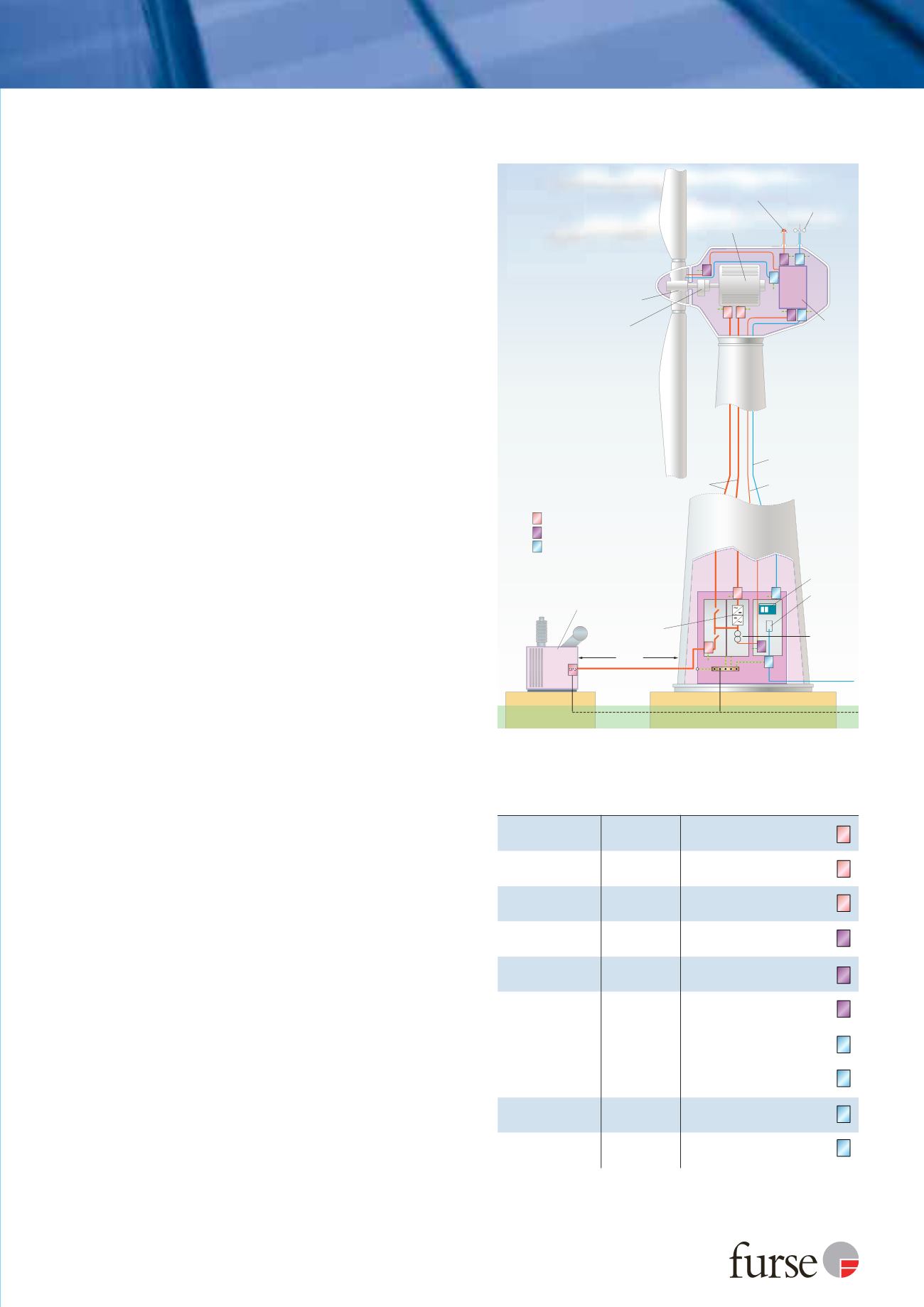
Protection follows the Lightning Protection Zones (LPZ)
concept established in BS EN/IEC 62305 and IEC 61400,
with equipment sited in internal zones up to LPZ 2 (see
Figure 8 & Table 3 for specific locations).
Power line protection
Lightning current/equipotential bonding SPDs
(minimum Type 1) are required at LPZ boundary LPZ 0
to LPZ 1 to counter partial lightning currents resulting
from a direct lightning strike.
Transient overvoltage SPDs (minimum Type 2) are
required at LPZ boundary LPZ 1 to LPZ 2 to protect
critical electronic systems.
The SPD selected should be suitable for the voltage of
the line. Furse
ESP WT Series
protectors apply at 690 V
with Furse
ESP D1 Series
or Furse
ESP M1 Series
protectors covering 230 V/400 V lines (see Table 3).
These power line protectors offer low let-through
voltage protection creating a safe area downstream of
minimum LPZ 2, meeting the requirements for wind
turbines.
SPDs should be installed on the line side, as close as
possible to the equipment being protected.
Where connected downstream equipment is > 10 m
away, a second SPD should be installed at the
subsequent equipment (in line with guidance in
DD CLC/TS 50539-22:2010).
If the main HV transformer is housed separately from
the wind turbine, incoming/outgoing lines from the
turbine
and
the HV transformer should be protected
(minimum LPZ 0 to LPZ 1, or where control system
electronics are installed LPZ 0 to LPZ 2).
Data/signal/telecoms line protection
SPDs should be installed to protect data, signal
and telecoms lines in the wind turbine and where
appropriate, the HV transformer.
A wide range of Furse SPDs is available for this
purpose, including the the
ESP SL Series
and
ESP D, E, H Series
protectors (see Table 3 for specific
application).
The SPD selected should be compatible with the system
to be protected, and offer sufficient protection to
reduce overvoltages below the immunity threshold of
the protected equipment. The SPD must not impede
system performance and must be able to survive
repeated transients.
The SPD should be installed as close as possible to the
point of entry/exit of the incoming/outgoing line.
Where connected equipment is > 10 m from the
incoming/outgoing line, a second SPD should be
installed at any subsequent connected equipment.
SPD
SPD
SPD
SPD
SPD
SPD SPD
SPD
SPD
SPD
LPZ 2
LPZ 1
LPZ 0
LPZ 1
LPZ 2
LPZ 1
LPZ 0
Gearbox
Power line 690V
Power line 230V
Data line
Hub controls
Transformer
>10 m
Frequency
converter
Modem
Auxilliary
transformer
690V to
230V
Wind
turbine
control
system
Control
cabinet
Anemometer
Aviation
warning
lights
Generator
SPD
SPD
SPD
Power line SPD 230V
Power line SPD 690V
Data line SPD
SPD
SPD
SPD
SPD
Figure 8: Application of SPDs within a typical wind turbine
environment
Table 3: SPD requirement according to component to be protected.
SPD
SPD
P
SPD
P
SPD
SPD
SPD
SPD
SPD
SPD
SPD