


 251 / 300

TSC-0912 - 09.10.12
NEW
NEW
Furse, Wilford Road, Nottingham, NG2 1EB • Tel: +44 (0)115 964 3700 • Email:
enquiry@furse.com• Web:
www.furse.comESP PV Series
NEW
Technical specification
1
The maximum transient voltage let-through of the protector
throughout the test, per mode.
2
The electrical system, external to the unit, may constrain the
actual current rating achieved in a particular installation.
3
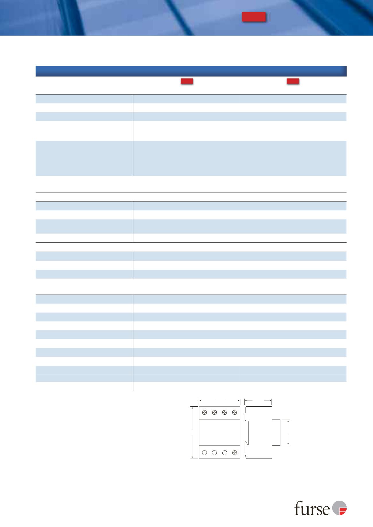
The remote signal contact (removable) adds 10 mm
to height.
72 mm
4 TE
90 mm
45 mm
51 mm
Standard
depth 68 mm
Electrical specification
ESP DC550/12.5/PV
ESP DC1000/12.5/PV
Maximum DC voltage
(RMS/DC)
550 V
1000 V
Short circuit withstand capability
25 kA/50 Hz
Leakage current
(to earth)
< 2.5 mA
Volt free contact
- current rating
- nominal voltage
(RMS)
Screw terminal
0.5 A
250 V
Back up fuse
Fuses specifically designed for use on PV systems are recommended. Determine the most appropriate back up
fuse from assessment of the nominal current of the PV module, and the open circuit voltage of the PV array:
1. multiply the nominal current of the photovoltaic module by a factor of 1.4 and select the closest, higher
value fuse to the calculated figure.
2. multiply the open circuit voltage of the PV array by a factor of 1.2 and ensure that the selected fuse has a
higher voltage withstand than the calculated figure.
Transient specification
ESP DC550/12.5/PV
ESP DC1000/12.5/PV
Type 1 (BS EN/EN), Class I (IEC)
Nominal discharge current 8/20 µs (per mode)
I
n
20 kA
Let-through voltage
U
p at
I
n
1
< 2.0 kV
< 2.6 kV
Impulse discharge current 10/350 µs
I
imp
(per mode)
2
12.5 kA
Let-through voltage
U
p at
I
imp
1
< 1.7 kV
< 2.4 kV
Type 2 (BS EN/EN), Class II (IEC)
Nominal discharge current 8/20 µs (per mode)
I
n
20 kA
Let-through voltage
U
p at
I
n
1
< 2.0 kV
< 2.6 kV
Maximum discharge current
I
max (per mode)
2
40 kA
Mechanical specification
ESP DC550/12.5/PV
ESP DC1000/12.5/PV
Temperature range
-40 to +80 ºC
Connection type
Screw terminal
Conductor size
(stranded)
25 mm
2
Earth connection
Screw terminal
Volt free contact
Connect via screw terminal with conductor up to 1.5 mm
2
(stranded)
Degree of protection
(IEC 60529)
IP20
Case material
Thermoplastic, UL94 V-0
Mounting
Indoor, 35 mm top hat DIN rail
Weight -
unit
0.38 kg
0.59 kg
-
packaged
0.48 kg
0.69 kg
Dimensions to DIN 43880 - HxDxW
3
90 mm x 68 mm x 72 mm (4TE)