


 261 / 300

TSC-0912 - 09.10.12
IMPROVED
IMPROVED
IMPROVED
Furse, Wilford Road, Nottingham, NG2 1EB • Tel: +44 (0)115 964 3700 • Email:
enquiry@furse.com• Web:
www.furse.comESP RF Series
ESP RF BK1
Straight mounting bracket, 53 x 26.3 x 3 mm
Two M4 clearance mounting holes, 16.3 mm apart
ESP RF BK2
90° mounting bracket, 33 x 26.3 x 3 mm,
20 x 26.3 x 3 mm
Two M4 clearance mounting holes, 16.3 mm apart, 14 mm from
fold line
ESP RF BK3
90° mounting bracket, 50 x 24 x 1.5 mm, 60 x 24 x 1.5 mm
Two M5 clearance mounting holes, 40 mm apart
ESP RF BK4
90° quad mounting bracket, 50 x 24 x 1.5 mm,
210 x 24 x 1.5 mm
Five M5 clearance mounting holes, various spacings
(Mounting brackets supplied with screws for fixing to protector)
Technical note
The high level of protection
offered by these units comes from
the addition of a high pass filter
circuit which gives a very low let-
through voltage. It should be
noted that due to this high pass
filter circuit no DC power can pass
along the transmission line. This is
referred to as “DC blocked”.
Protectors with other connectors
are available.
For RF applications where DC power is
present on the coaxial cable, use the
alternative RF protectors. The ESP
CCTV/B and ESP CCTV/T are suitable for
use on coaxial (or twisted pair) CCTV
lines. For coaxial CATV lines, use the
ESP CATV/F.
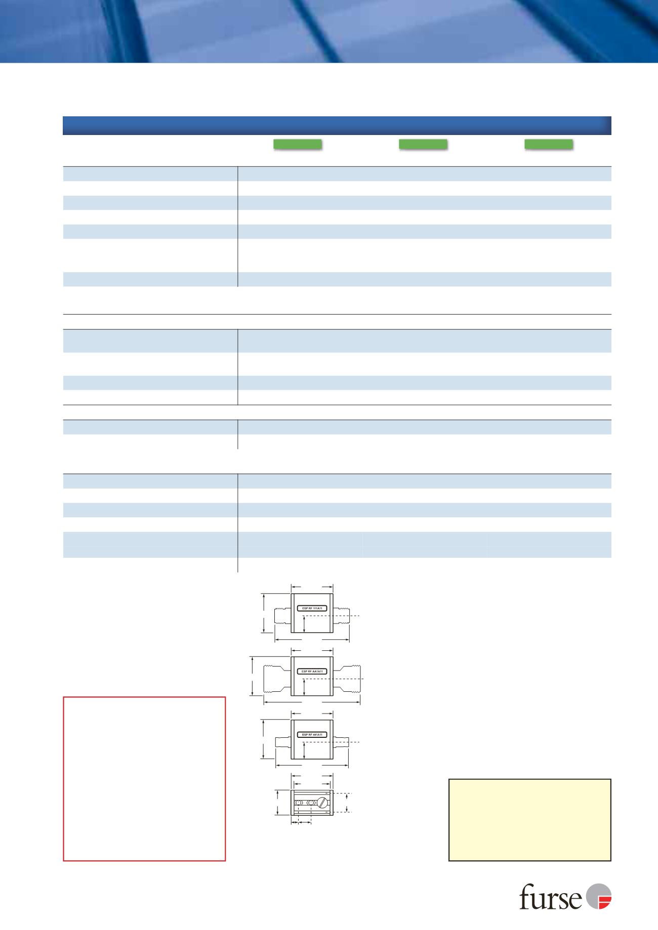
43 mm
43 mm
43 mm
43 mm M3 threaded
channel,
5 mm deep
M3 threaded
channel,
5 mm deep
37 mm
40 mm
40 mm
40 mm
25.8 mm
19.3 mm
77 mm
77 mm
9-13 mm
7 mm
min.
95 mm
17.3 mm
17.3 mm
17.3 mm
Technical specification
1
The maximum transient voltage let-through of the protector
throughout the test (±10%). Response time < 10 ns. This
let-through voltage represents a deviation from the applied
signal voltage, present at the time of the test.
2
Test to IEC 61000-4-5:2006, ITU-T (formerly CCITT) K.20,
K.21 and K.45,Telcordia GR-1089-CORE, Issue 2:2002,
ANSI TIA/EIA/IS-968-A:2002 (formerly FCC Part 68).
3
The installation and connectors external to the protector may
limit the capability of the protector.
Electrical specification
ESP RF 111A11
ESP RF AA1A11
ESP RF 441A11
Maximum working voltage
U
c
(RMS)
86 V
Maximum transmitted power
(RMS)
150 W
Characteristic impedance
50
Ω
Bandwidth
50-2700 MHz
Voltage standing wave ratio
≤
1.2
Insertion loss over bandwidth -
50-500 MHz
Insertion loss over bandwidth
-
500-1,600 MHz
Insertion loss over bandwidth
-
1.6-2.7 GHz
≤
0.4 dB
≤
0.2 dB
≤
0.4 dB
Maximum power
150 W
Transient specification
ESP RF 111A11
ESP RF AA1A11
ESP RF 441A11
Let-through voltage
(all conductors)
1
U
p
C2 test 4 kV 1.2/50 µs, 2 kA 8/20 µs to
BS EN/EN/IEC 61643-21
24 V
C1 test 1 kV, 1.2/50 µs, 0.5 kA 8/20 µs to
BS EN/EN/IEC 61643-21
15 V
B2 test 4 kV 10/700 µs to BS EN/EN/IEC 61643-21
15 V
5 kV, 10/700 µs
2
20 V
Maximum surge current
3
D1 test 10/350 µs to BS EN/EN/IEC 61643-21
1 kA
8/20 µs to ITU-T K.45:2003, IEEE C62.41.2:2002
10 kA
Mechanical specification
ESP RF 111A11
ESP RF AA1A11
ESP RF 441A11
Temperature range
-40 to +80 ºC
Connection type
N female
7⁄16 DIN female
BNC female
Earth connection
Via mounting fixtures
Case material, finish
Aluminium, white bronze plated
Weight -
unit
150 g
220 g
120 g
-
packaged
170 g
240 g
160 g
Dimensions