


 260 / 300

TSC-0912 - 09.10.12
Furse, Wilford Road, Nottingham, NG2 1EB • Tel: +44 (0)115 964 3700 • Email:
enquiry@furse.com• Web:
www.furse.comESP RF Series
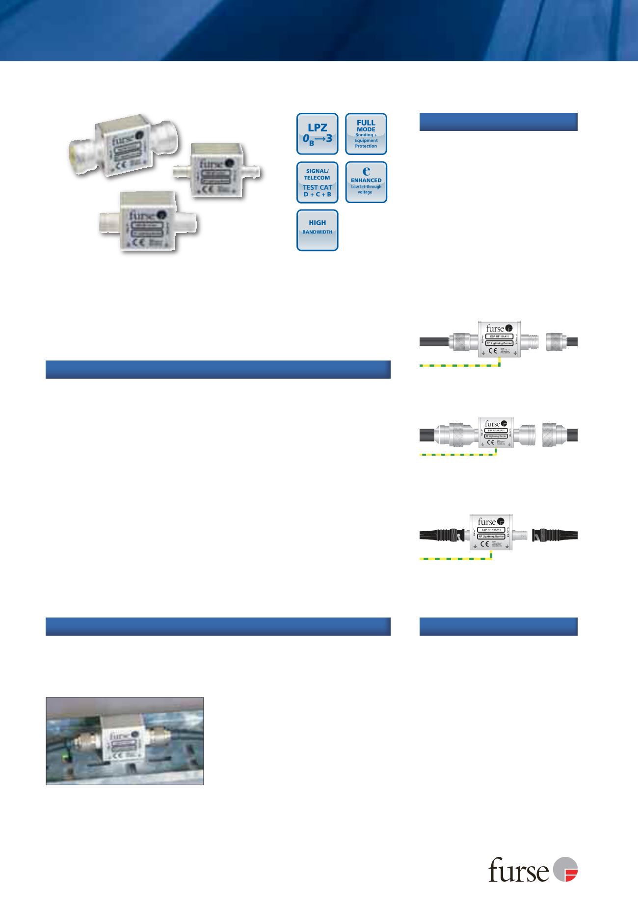
ESP RF 111A11 with N female connectors
installed in series
DIRTY
CLEAN
From line
To
equipment
Earth
ESP RF AA1A11 with 7/16 DIN female
connectors installed in series
DIRTY
CLEAN
To
equipment
Earth
ESP RF 111A11 installed on a coaxial cable
running between an antenna and an RF receiver.
Note the earth lead (behind the cable tray)
attached to the mounting fixture
From line
ESP RF 441A11 with BNC female connectors
installed in series
DIRTY
CLEAN
From line
To
equipment
Earth
Very low let-through voltage (enhanced protection to BS EN 62305)
between all lines - Full Mode protection
Full mode design capable of handling partial lightning currents as well
as allowing continual operation of protected equipment
Repeated protection in lightning intense environments
Superior transient protection to both Gas Discharge Tube (GDT) and
Quarter Wave Stub (QWS) based protectors
Very low attenuation and near unity VSWR over a wide range of
frequencies ensure the protectors do not impair system performance
Wide bandwidth means a single product is suitable for a range
of applications
Available with N, 7/16 DIN and BNC connectors
Easily mounted and earthed via fixtures on the base of the unit that
accept M3 and M5 screws or via mounting brackets
Additional mounting plates give increased flexibility
Robust white bronze plated aluminium housing (silver plate option)
Features and benefits
Combined Category D, C, B tested protector (to BS EN 61643)
suitable for RF systems (of power up to 150 W) using coaxial cables
at frequencies between 50 MHz and 2.7 GHz to provide effective
protection without impairing system performance. For use at
boundaries up to LPZ
0
B
to protect against flashover (typically the
service entrance location) through to LPZ 3 to protect sensitive
electronic equipment.
ESP RF BK1
Straight mounting plates
ESP RF BK2
90° angled mounting plates
ESP RF BK3
Bulkhead through mounting plate
(single)
ESP RF BK4
Bulkhead through mounting plate
(for 4 products)
ESP RF GDT-A
Replacement gas discharge tube
Accessories
In a building, connect in series
with the coaxial cable near where
it enters or leaves the structure, or
close to the equipment being
protected. This should be as close
as possible to the system’s earth
star point (to enable a good
connection to earth). On a mast,
connect in series with the coaxial
cable near the antenna/dish being
protected.
Install in a radio communications
room, an existing cabinet or a
suitable enclosure.
Installation
Use on coaxial cables to protect RF transmitter and receiver systems,
including electronics located at the antenna or dish. Typical examples
include cell sites, military communications, satellite earth stations, pager
systems and emergency services communications systems.
Application