


 77 / 100

Multiples of Rated Current (x I
n
)
Time (sec.)
10000.00
1000.00
100.00
10.00
1.00
0.10
0.01
1
2 3 5
10
20 30
100
1.13 1.45
Voltage across contacts
during opening of MCB
Maximum
Prospective
Fault
Current
Time
Current
Voltage
A
B
0
0 t
x
t
1
t
2
PowerSafe – Commercial & Industrial
77
Miniature Circuit Breakers (MCBs)
General Characteristics
Standard Conformity
EN 60898-1
Type / Series B C
Rated Current (In)
A 6-40 0.5 - 63* 0.5 - 63*
Rated Voltage (Ue)
V~ 240/415 240/415 240/415
Rated Frequency (f)
Hz 50
No. of Poles (Execution)
1P, 3P,
Rated Short Circuit Breaking Capacity 10 kA
Magnetic Release Setting
(3-5)In (5-10)In (10-20)In
Rated Insulation Voltage (Ui)
V 660
Rated Impulse Voltage (Uimp)
kV 4
Electrical / Mechanical Endurance
<32A 20000
(no. of operations)
>32A 10000
Ambient Working Temperature (oC)
-5°C to 55°C
Vibration
g 3
Protection Class
IP-20
Installation Position
Vertical / Horizontal
Mounting Clip
on DIN Rail (35mm x 7.5mm)
Case & Cover
Moulded, flame-retardant
thermoplastic material
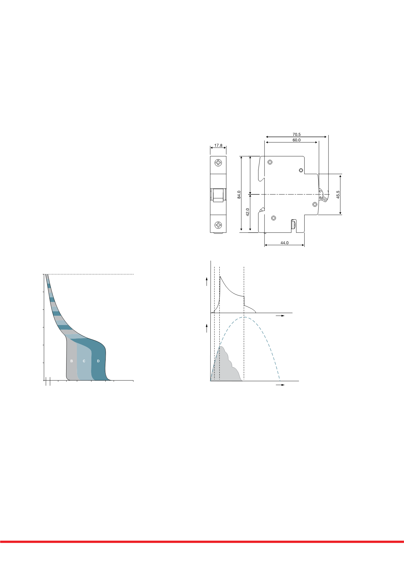
Tripping Characteristics
Based on the Tripping Characteristics, MCBs are available in
‘B’, ‘C’ and ‘D’ curve to suit different types of applications.
‘B’ Curve: for protection of electrical circuits with equipment
that does not cause surge current (lighting and distribution circuits).
Short circuit release is set to (3-5)
‘C’ Curve: for protection of electrical circuits with equipment
that causes surge current (inductive loads and motor circuits).
Short circuit release is set to (5 - 10) In
‘D’ Curve: for protection of electrical circuits which causes
high inrush current, typically 12-15 times the thermal rated
current (transformers, X-ray machines etc.)
Short circuit release is set to (10 - 20) In
Current Limiting Design
In a current limiting breaker, the tripping & arc control
mechanism are so designed that under short circuit conditions,
the contacts are physically separated and the electrodynamic forces
set up by fault current, assist the extinction in less than half cycle.
The figure shows the current limiting effect of circuit breakers.
Fault Traces for Voltage & Current
0 = Point of fault initiation
tx = Contact opening time (i.e., creation of arc)
t1 = Current / Voltage peak (i.e., current limitation)
t2 = Time to total extinction of arc (i.e., complete shutdown
of fault current)
Cable Capacity
Cable clamp 25mm2