


 74 / 100

74
HAVELLS
Type ‘A’ and ‘B’ Surge Protection Devices
Electrical specification
(PS) ESP 240 M1
(PS) ESP 415 M1
Nominal voltage - Phase-Neutral Uo (RMS)
240V
240V
Maximum voltage - Phase-Neutral Uc (RMS)
280V
280V
Temporary Overvoltage TOV U
T
1
350V
350V
Short circuit withstand capability
25kA, 50Hz
Working voltage (RMS)
200-280V
346-484V
Frequency range
47-63Hz
Max. back-up fuse (see installation instructions)
125A
Leakage current (to earth)
<250µA
Indicator circuit current
<10mA
Volt free contact
2
– current rating
– nominal voltage (RMS)
Screw terminal
1A
250V
Transient specification
Type 1 (BS EN/EN), Class I (IEC)
(PS) ESP 240 M1
(PS) ESP 415 M1
Nominal discharge current 8/20µs (per mode) In
20kA
Let-through voltage Up at In
1
900V
900V
Impulse discharge current 10/350µs Iimp (per mode)
2
4kA
Let-through voltage Up at Iimp
1
750V
750V
Impulse discharge current (per phase) limp
3
6.25kA
Type 2 (BS EN/EN), Class II (IEC)
Nominal discharge current 8/20µs (per mode) In
20kA
Let-through voltage Up at In
1
900V
900V
Maximum discharge current Imax (per mode)
2
40kA
Maximum discharge current Imax (per phase)
80kA
Type 3 (BS EN/EN), Class III (IEC)
Let-through voltage Up at Uoc
1
of 6kV 1.2/50µs and Isc of 3kA 8/20µs (per mode)
4
600V
600V
Mechanical specification
(PS) ESP 240 M1
(PS) ESP 415 M1
Temperature range
–40 to +70ºC
Connection type
Screw terminal
Conductor size (stranded)
16mm
2
Earth connection
Screw terminal
Volt free contact
Connect via screw terminal with conductor up to 2.5mm
2
(stranded)
Degree of protection (IEC 60529)
IP20
Case material
Steel
Weight – unit
0.6kg
1.0kg
– packaged
0.7kg
1.1kg
1
Temporary Overvoltage rating is for a maximum duration of 5 seconds tested to BS EN/EN/IEC 61643.
2
Minimum permissable load is 5V DC, 10mA to ensure reliable operation.
1
4HE MAXIMUM TRANSIENT VOLTAGE LET THROUGH OF THE PROTECTOR THROUGHOUT THE TEST ¢ PHASE TO NEUTRAL PHASE TO EARTH AND NEUTRAL TO EARTH
2
The electrical system, external to the unit, may constrain the actual current rating achieved in a particular installation.
3
Rating is considered as the current capability of the protector for equipotential bonding near the service entrance.
4
Combination wave test within BS 6651:1999 App. C, Cats C-Low & B-High, IEEE C62.41-2002 Location Cats C1 & B3, SS CP 33:1996 App.
F, AS 1768-1991 App. B, Cat B, UL1449 mains wire-in.
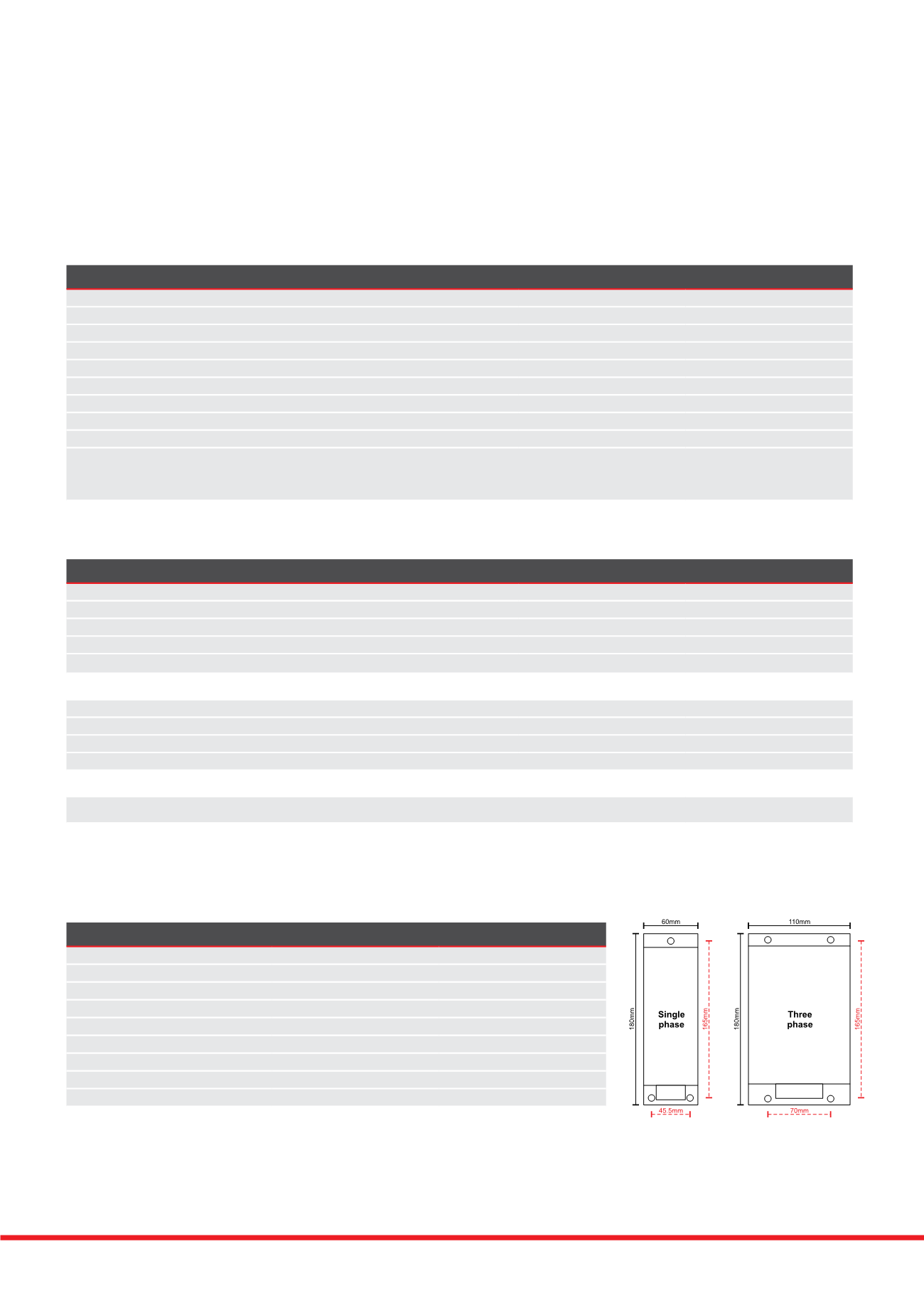
Depth=73mm
M5 clearance
NOTE:
The unit takes
up 20mm of
the length of
the fixing
screw.
Depth=73mm
M5 clearance
NOTE:
The unit takes
up 20mm of
the length of
the fixing
screw.
If you desire a protector with an extra high maximum surge current use the ESP M2
or M4 series. If your supply is fused at 16 amps, or less, the in-line protectors (ESP
240 (or 120-5A (or -16A) and their ready boxed derivatives) may be more suitable.
If you need to mount the display panel separately from the main protector unit, use
the ESP M1R series.
Surge Protection devices have been designed to be installed on the left hand
side of all distribution boards and MCCB panelboards.