


 96 / 413

4/30
Presentation
The
TSX CFY 11/21
stepper motor axis control range is designed for machines
requiring simultaneous motion control by stepper motor and sequential control by
PLC.
The
TSX CFY 11
module controls 1 axis (channel 0) via a translator (amplifier for
stepper motor) or Lexium 32C/M servo drive. The
TSX CFY 21
module controls 2
axes (channels 0 and 1).
These modules are compatible with the Lexium 32C/M servo drive or translators
with:
b
5
V RS 422 or TTL inputs (negative logic)
b
5
V
c
NPN open collector or RS 422 outputs.
In a Premium PLC configuration, the number of TSX CFY motion control modules
must be added to that of the other application-specific modules (communication,
counting, axis control and weighing).
Description
The front panels of
TSX CFY 11/21
stepper control modules comprise:
1
One 15-way SUB-D connector per channel for connecting:
v
Translator or Lexium 32C/M servo drive inputs
v
Translator or Lexium 32C/M servo drive outputs
v
Translator or Lexium 32C/M servo drive input power supply
2
One 20-way HE 10 connector for connecting:
v
Auxiliary inputs: per axis, homing cam, emergency stop, limit switches (+ and -),
event, external stop
v
Brake outputs (1 per axis)
v
Sensor and preactuator external power supply
3
Rigid casing, which:
v
Holds electronic cards
v
Locates and locks the module in its slot
4
Module diagnostic LEDs:
v
Module diagnostics:
-
Green RUN LED: module operating
-
Red ERR LED, internal fault, module failure
-
Red I/O LED, external fault
v
Axis diagnostics:
- 2
green CH
p
LEDs: axis diagnostics available
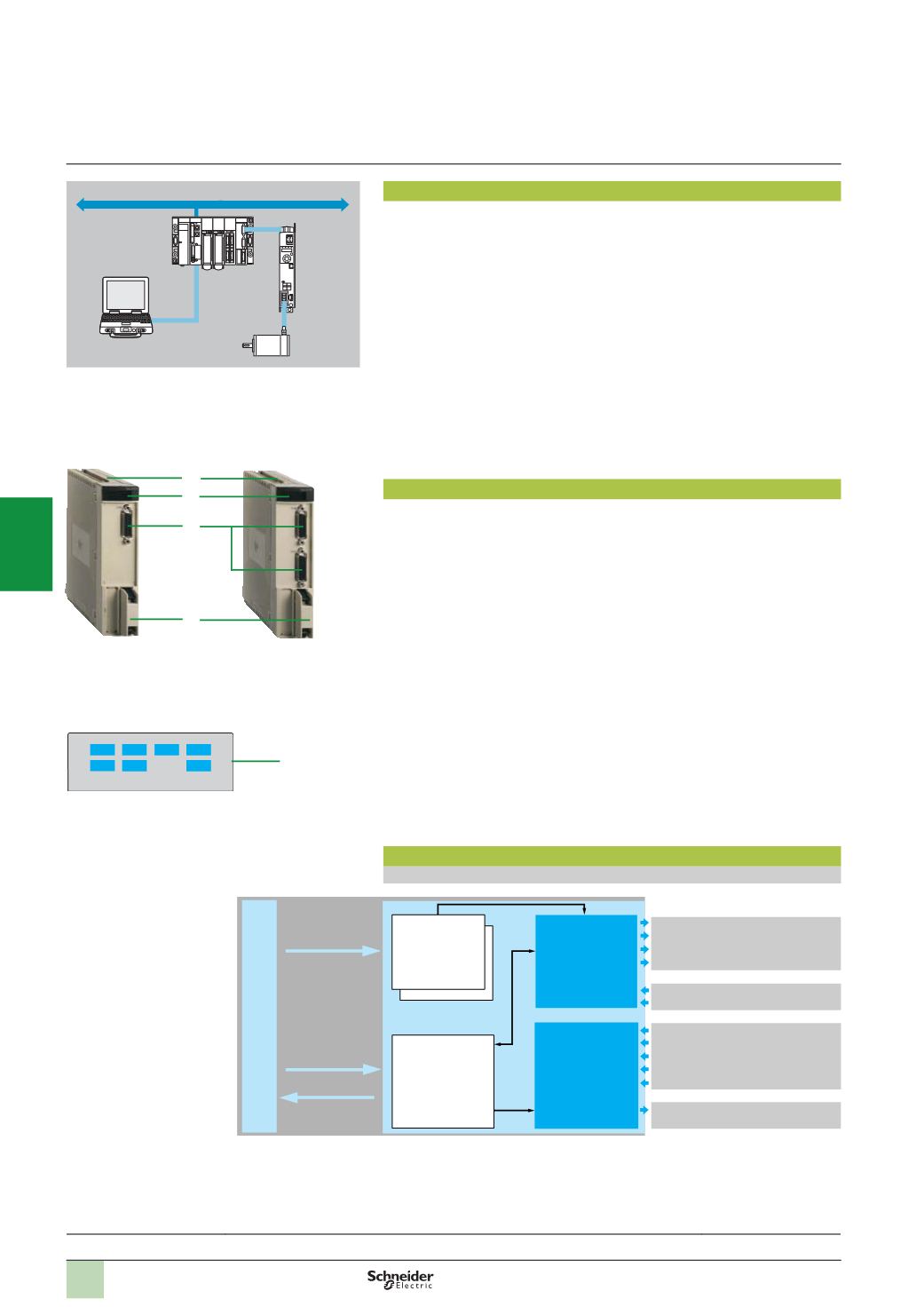
Operation block diagram
Block diagram of an axis
Stepper motor control modules are set up using Unity Pro or PL7 Junior/Pro software.
CH2
ERR
CH0 RUN
CH3 CH1
I/O
4
Pulse generator
Auxiliary I/O
processing
Configuration
parameters
Processing
Configuration
+ adjustment
%
KW.%MW
SMOVE function
%
O, %QW
%
I, %IW
Motor
Modicon
Premium
Presentation,
description,
operation
3
4
1
2
TSX CFY 11
TSX CFY 21
Modicon Premium automation
platform
TSX CFY 11/21 motion control modules for
stepper motors
Lexium
32
C/M
servo
drive
Architectures:
page 4/31
References:
pages 4/32 ...
Translator enable output
A/B pulse outputs
Loss of step reset output
Boost output
Translator fault input
Loss of step check input
Cam input (homing)
+ and – limit switch input
Emergency stop input
Event input
External stop input
Brake output
2
1
3
4
5
6
7
8
9
10