


 235 / 413

5/101
Description
TSX P57
p
53/54
M
,
TSX P57
p
823
M
processors incorporating a Fipio bus link have
the following on the front panel:
1
A 9-way SUB-D connector for connection to the bus via the
TSX FPACC2
/
12
connector.
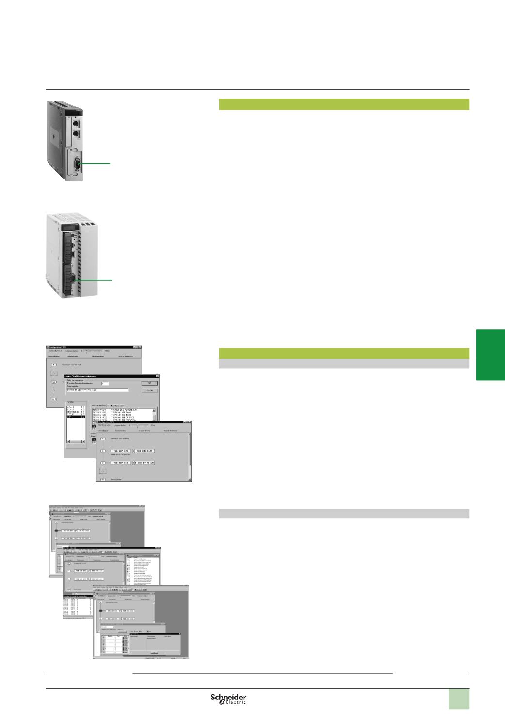
Software setup
Configuration
Unity Pro or PL7 Junior/Pro software offer configuration screens which enable the
declaration and immediate and intuitive configuration of the remote devices
connected on the Fipio bus:
1
Each circle represents one connection point.
2
Clicking on a circle accesses the catalogue of devices which can be connected.
3
Once confirmed, the Fipio bus configuration will appear.
Processors equipped with the integrated Fipio link can manage up to 128 connection
points on the bus (addresses 0 to 127).
See page 5/102 for the table detailing limitations according to processor and type of
device.
Diagnostics
The diagnostic functions of the Fipio bus, integrated in the Unity Pro or PL7 Junior/Pro
software, very quickly identify a fault on:
b
The bus medium
b
Remote devices
1
A graphic representation of the architecture displays the defective devices in red.
2
More detailed diagnostics can be accessed by double-clicking.
3
In addition, specific screens can display an overview of all the faults appearing on
the bus or on any device. On request, these faults can be recorded for later
analysis.
Modicon Premium automation
platform
Fipio bus manager function
Description,
software setup
2
1
3
1
2
3
1
TSX P57 153M/154M
TSX P57 454/554M
1
Presentation:
page 5/100
Maximum configuration:
page 5/102
References:
page 5/103
Fipio bus configuration
Fipio bus diagnostics
2
1
3
4
5
6
7
8
9
10