


 161 / 356

B-23
Distribution
Busbar calculation
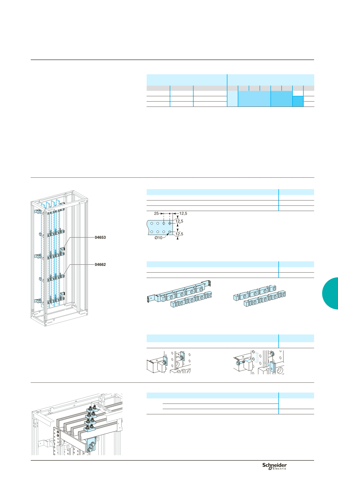
The bars are secured by insulated supports. Three
fixed supports, attached to the framework, are
mandatory.
If necessary, additional free supports may be used.
Mounting chocks screwed to the busbars rest on one of
the fixed supports.
The table opposite indicates:
b
the number and size of the bars to be used,
depending on the permiss ble current level in the
busbars
b
the number of supports required, depending on the
rated short-time withstand current (Icw).
For more information on busbar calculations, see page
D-25.
Permissible current
for switchboards
Size of bars No. of supports Icw
(kA rms / 1 s)
IP
y
31
IP > 31
y
25
y
30
y
40
y
50
y
60
y
65
y
75
y
85
1200
1080
1 bar, 50 x 10
1400
1250
1 bar, 60 x 10
3
5
7
9
1800
1600
1 bar, 80 x 10
Note:
the permissible current values for the busbars are given for an ambient temperature of
35 °C around the switchboard.
Busbar selection
Flat busbars, L = 1675 mm
DD381503
Designation
Cat. no.
Copper bar with holes, 50 x 10 mm
04525
Copper bar with holes, 60 x 10 mm
04526
Copper bar with holes, 80 x 10 mm
04528
DD381505
Busbar supports
Three fixed supports are required to maintain the vertical busbars. If more than three
supports are required, use additional free supports.
Designation
Cat. no.
Fixed support for rear flat busbars
04653
Free support (additional)
04662
DD380732
DD381652
04653.
04662.
Busbar chocks
Ametal mounting chock, 5 mm thick, is screwed to the bar. It rests on a fixed support
and maintains the position of the bar.
Icw 40 kA rms / 1 s.
The bars are secured by three mandatory fixed supports (3 x
04653) and two free supports (2 x 04662).
Designation
Cat. no.
100 mounting chocks (5 mm) for busbars
04669
DD380815
DD380733
Chocking for one bar per phase.
Chocking for two bars per phase.
Horizontal-busbar connections
DD381504
Designation
Cat. no.
Connection
y
1600 A for horizontal bars, 10 mm thick
width of horizontal bars
y
80 mm
04636
(1)(2)
width of horizontal bars > 80 mm
04636
(2)
+ 04642
(1)
(1)
A part of the connection must be made.
(2)
Catalogue number 04636 includes 1 connection only. Order 1 connection per phase.
Rear flat busbars up to 1600 A
Flat busbars, 10 mm thick
Main distribution