


 156 / 356

B-18
Distribution
Busbar calculation
The bars are secured by insulated supports. Three
fixed supports, attached to the framework, are
mandatory.
If necessary, additional free supports may be used.
The bars rest on a bottom support.
The table opposite indicates:
b
the number and size of the bars to be used,
depending on the permissible current level in the
busbars
b
the number of supports required in a cubicle,
depending on the rated short-time withstand current
(Icw).
Permissible current
for switchboards
No. of bars /
phase
No. of supports
Icw
(kA rms / 1 s)
IP
y
31
IP > 31
y
15
y
20
y
25
y
30
y
40
y
50
290
240
1 bar, 20 x 5 mm
7
(1)
430
350
1 bar, 32 x 5 mm
5 7 9
(1)
800
750
1 bar, 60 x 5 mm
1000
900
1 bar, 80 x 5 mm
7
1400
1250
2 bars, 60 x 5 mm
3
5
1800
1600
2 bars, 80 x 5 mm
(1)
(kA rms / 0,6s)
Note:
the permissible current values for the busbars are given for an ambient temperature of
35 °C around the switchboard.
For more information on busbar calculations, see page D-25.
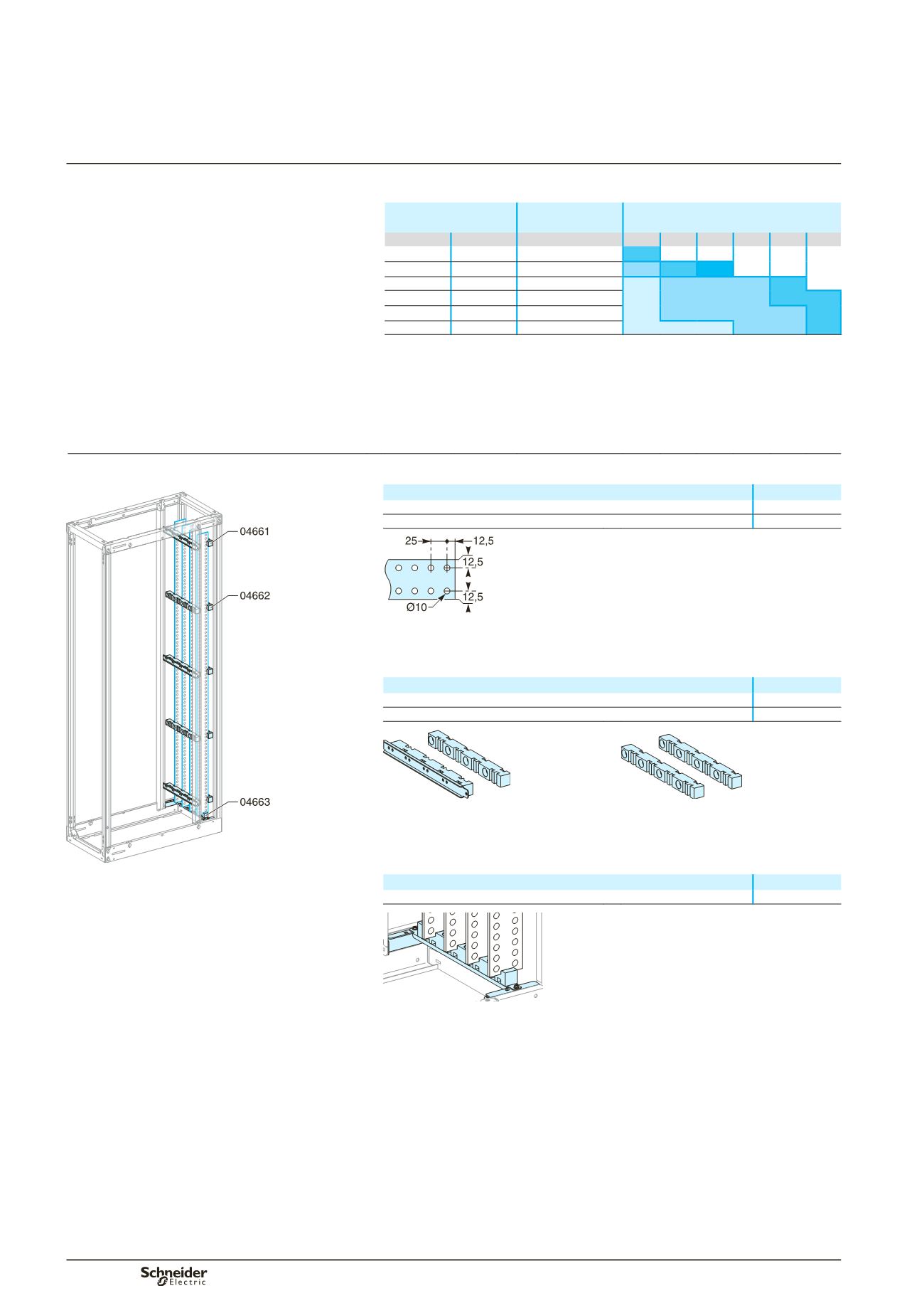
Busbar selection
Flat busbars, L = 1675 mm
DD380724
Designation
Cat. No.
Copper bar with holes, 60 x 5 mm
04516
Copper bar with holes, 80 x 5 mm
04518
DD381505
Busbar supports
Three fixed supports are required to maintain the busbars. If more than three
supports are required, use additional free supports.
Designation
Cat. No.
Fixed support for lateral flat busbars
04661
Free support (additional)
04662
DD380829
DD381650
04661.
04662.
Busbar chocks
The bottom support maintains the bars in position.
It is not considered a busbar support.
Icw 30 kA rms / 1 s.
The bars are secured by three mandatory fixed supports and
two free supports.
Designation
Cat. No.
Bottom support for lateral flat busbars
04663
DD380728
Note:
when connecting 5 mm flat bars to horizontal busbars, part no. 04663 is not required.
Lateral flat busbars
up to 1600 A
Busbars 5 mm thick
Main distribution