


 159 / 356

B-21
Distribution
Lateral flat busbars
up to 3200 A
For 300 mm width framework
Busbar calculation
The bars are secured by insulated supports. Three
fixed supports, attached to the framework, are
mandatory. If necessary, additional free supports may
be used.
The bars rest on a bottom support.
The table opposite indicates:
b
the number and size of the bars to be used,
depending on the permissible current level in the
busbars
b
the number of supports required in a cubicle,
depending on the rated short-time withstand current
(Icw).
Permissible
current
for switchboards
No. of bars /
phase
No. of supports
Icw
(kA rms / 1 s)
IP
y
31 IP > 31
y
15
y
20
y
25
y
30
y
40
y
50
800
750
1 bar, 60 x 5 mm
1000
900
1 bar, 80 x 5 mm
7
1400
1250 2 bars, 60 x 5 mm
3
5
1800
1600 2 bars, 80 x 5 mm
Permissible
current
for switchboards
No. of bars /
phase
No. of supports
Icw
(kA rms / 1 s)
IP
y
31 IP > 31
y
25
y
30
y
40
y
50
y
60
y
65
y
75
y
85
1800
1600 1 bar. 80 x 10 mm
2150
1900 1 bar 100 x 10 mm
7
9
2820
2500 2 bars, 80 x 10 mm
3
5
3300
2900 2 bars, 100 x 10 mm
7
Note:
the permissible current values for the busbars are given for an ambient temperature of
35 °C around the switchboard.
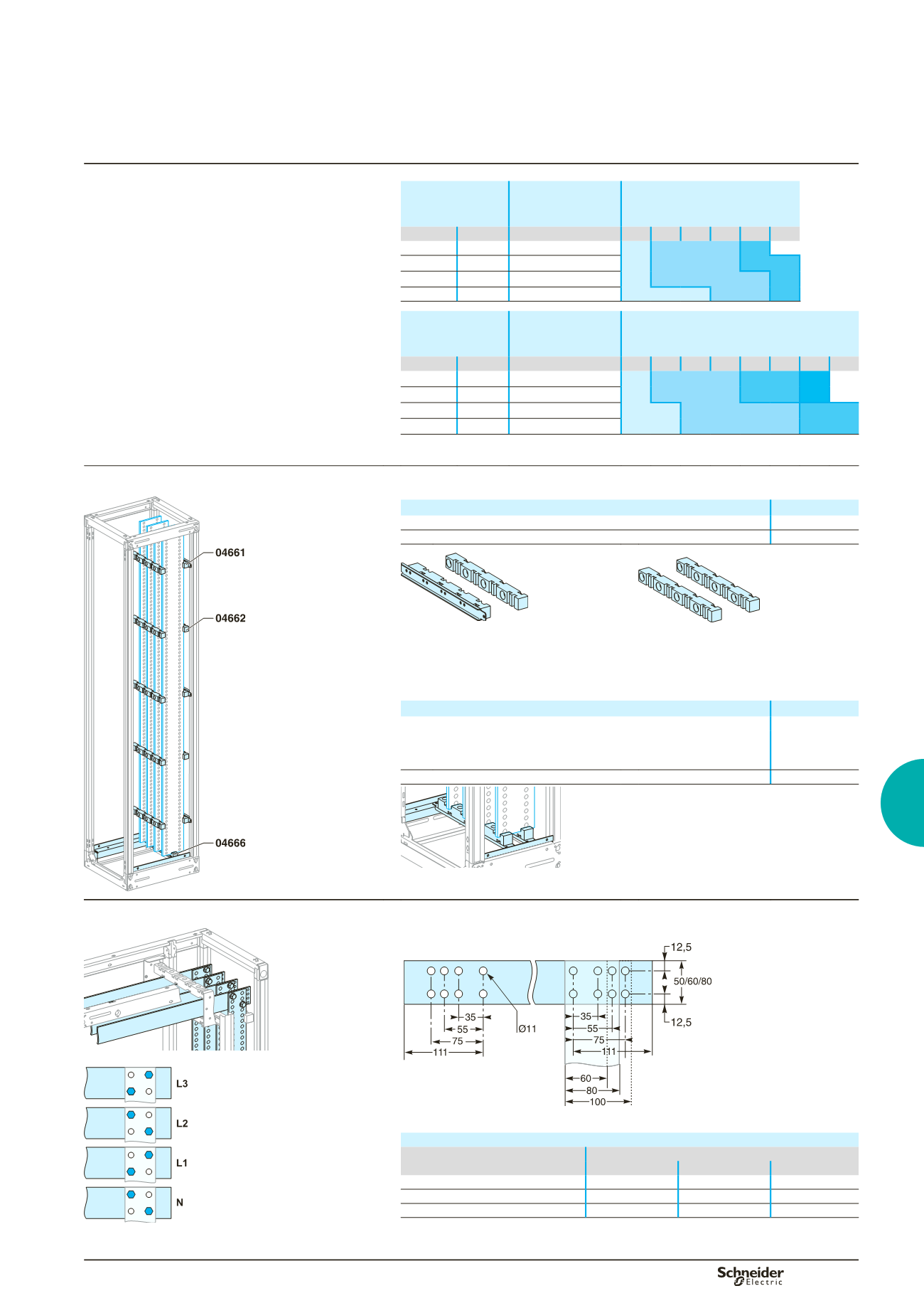
Busbar supports
Three fixed supports are required to maintain the busbars. If more than three
supports are required, use additional free supports.
DD383193
Designation
Cat. no.
Fixed support for lateral flat busbars
04661
Free support (additional)
04662
DD380829
DD381650
04661.
04662.
Busbar chocks
The bottom support maintains the bars in position.
It is not considered a busbar support.
Designation
Cat. no.
Bottom support for lateral flat busbars W = 300 mm
04666
all bars 5 mm width
1 bar. 80 x 10 mm
2 bars, 80 x 10 mm
Bottom support for busbar 100 x 10 mm
04666 + 04661
DD383194
Horizontal-busbar connections
Direct connection (75 mm between centres)
For busbars with 75 mm between centres, the bars must fully overlap.
DD383844
DD383400
DD383399
Drilling diagram for horizontal busbars, 10 mm thick.
Number of assembly screws (04645)
Vertical bars (mm)
Horizontal bars (mm)
50
60
80
50
2
2
2
60
-
2
2
80
-
-
3
For direction connection (75 or 115 mm between centres) with top horizontal
busbars, do not use the bottom support (06263, 06273 or 06283).
To satisfy safety clearances, the assembly points on adjacent
bars must be staggered as shown above.
Main distribution