


 158 / 356

B-20
Distribution
Lateral flat busbars
up to 3200 A
Busbars 10 mm thick
Busbar calculation
The bars are secured by insulated supports. Three
fixed supports, attached to the framework, are
mandatory. If necessary, additional free supports may be
used.
The bars rest on a bottom support.
The table opposite indicates:
b
the number and size of the bars to be used,
depending on the permissible current level in the
busbars
b
the number of supports required in a cubicle,
depending on the rated short-time withstand current
(Icw).
Above 2800 A (2500 Awith IP > 31), the busbars must
be doubled and installed in two busbar sections, side
by side. In this case, they must be interconnected by
three equipotential links.
Permissible
current
for switchboards
No. of bars /
phase
No. of supports
Icw
(kA rms / 1 s)
IP
y
31 IP > 31
y
25
y
30
y
40
y
50
y
60
y
65
y
75
y
85
1200
1080
1 bar, 50 x 10 mm
1400
1250
1 bar. 60 x 10 mm
7
9
1800
1600
1 bar. 80 x 10 mm
5
2050
1850
2 bars, 50 x 10 mm
3
2300
2000
2 bars, 60 x 10 mm
2820
2500
2 bars, 80 x 10 mm
Double busbars
3200
2820
2 x 1 bar, 80 x 10 mm
2 x 3
2 x 5
Note:
the permissible current values for the busbars are given for an ambient temperature of
35 °C around the switchboard.
For more information on busbar calculations, see page D-25.
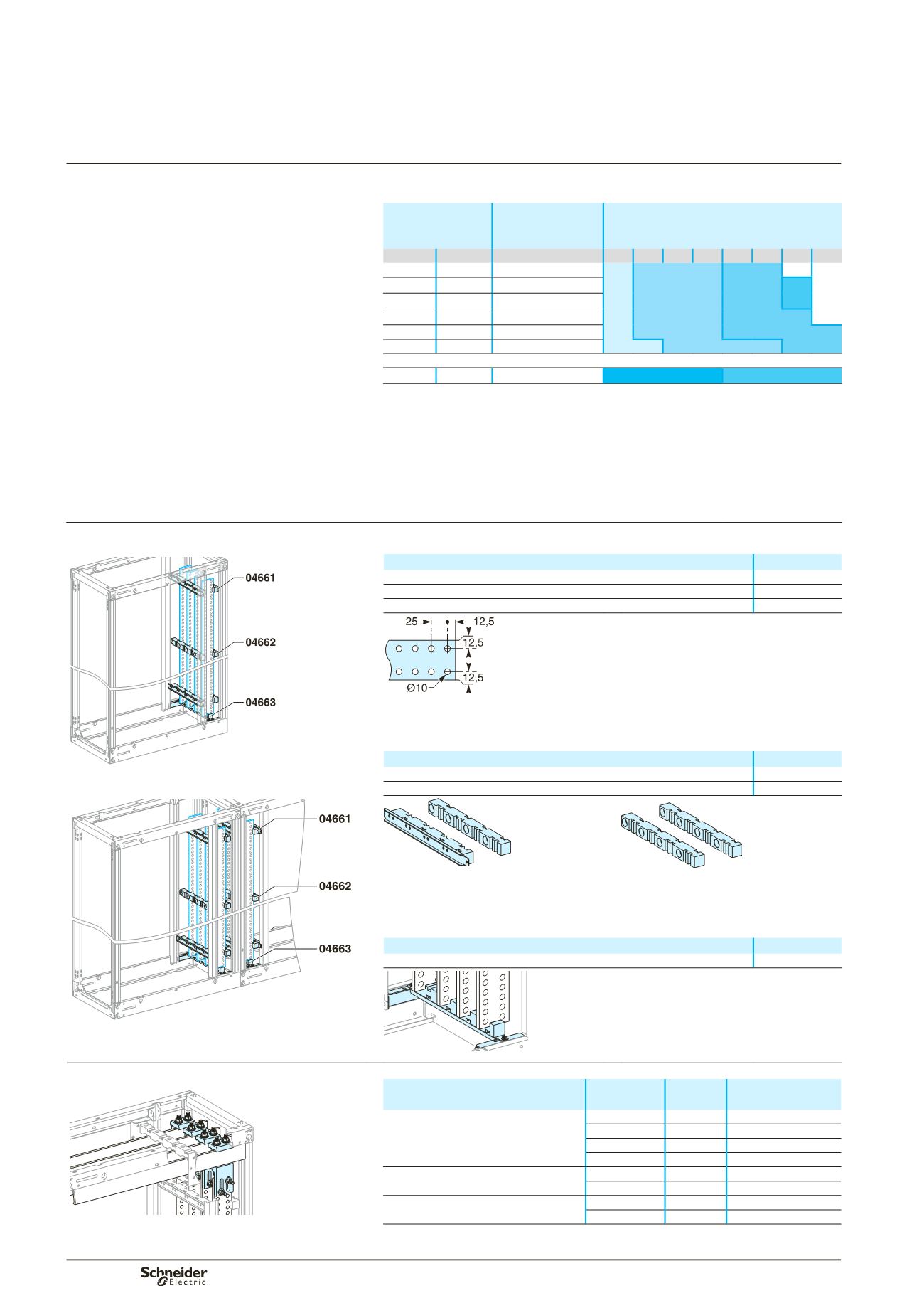
Busbar selection
Flat busbars, L = 1675 mm
DD381497
Designation
Cat. no.
Copper bar with holes, 50 x 10 mm
04525
Copper bar with holes, 60 x 10 mm
04526
Copper bar with holes, 80 x 10 mm
04528
DD381505
Busbar supports
Three fixed supports are required to maintain the busbars. If more than three
supports are required, use additional free supports.
Designation
Cat. no.
Busbars
y
1600 A (IP
y
31).
Fixed support for lateral flat busbars
04661
Free support (additional)
04662
DD381498
DD380829
DD381650
04661.
04662.
Busbar chocks
The bottom support maintains the bars in position.
It is not considered a busbar support.
Designation
Cat. no.
Bottom support for lateral flat busbars
04663
DD381124
Busbars up to 3200 A.
Horizontal-busbar connections
Connection to horizontal busbars, 10 mm thick.
DD381499
Designation
Horizontal
busbars
Vertical
busbars
Cat. no.
Connection between vertical busbars
(1 bar/phase) and horizontal busbars
W
y
80 mm 50/60 mm
04636
(1)
W > 80 mm 50/60 mm
04636
(1)
+ 04642
W
y
80 mm 80 mm
04637
(1)
W > 80 mm 80 mm
04637
(1)
+ 04642
Connection between vertical busbars
(2 bars/phase) and horizontal busbars
W
y
80 mm 50/80 mm
04637
(1)
W > 80 mm 50/80 mm
04637
(1)
+ 04642
Connection between double vertical
busbars and horizontal busbars
W
y
80 mm 80 mm
04636
(1)
x 2
W > 80 mm 80 mm
(04636
(1)
+ 04642) x 2
(1)
Catalogue numbers 04636 and 04637 include 1 connection only. Order 1 connection per
phase.
Main distribution