


 142 / 356

B-4
Horizontal busbars
Up to 1600 A
Flat copper bars 5 mm thick
Distribution
Busbar calculation
The bars are secured by insulated supports attached to
the framework.
The tables opposite indicate:
b
the number and size of the bars to be used,
depending on the permissible current level in the
busbars
b
the number of busbar supports for each type of
framework, depending on:
v
the size of the busbars
v
the rated short-time withstand current Icw.
For more information on busbar calculations, see page
D-23.
Number and size of copper busbars
Permissible current (A)
No. of bars / phase
IP
y
31
IP > 31
800
750
1 bar, 60 x 5
1000
900
1 bar, 80 x 5
1400
1250
2 bars, 60 x 5
1800
1600
2 bars, 80 x 5
Note:
the permissible current values for the busbars are given for an ambient temperature of
35°C around the switchboard.
Number of supports
Framework width
(mm)
Size of bars
(mm)
No. of supports
Icw
(kA rms / 1 s)
y
15
y
25
y
30
y
40
y
50
W = 650 mm
W = 650 + 150 mm
1 bar, 60 x 5
1 bar, 80 x 5
2
3
2 bars, 60 x 5
2 bars, 80 x 5
3
4
W = 300 mm
All sizes
1
2
W = 400 mm
All sizes
1
2
Note
: for a W = 800 mm framework, add a free support to the number of fixed supports given by
the table below.
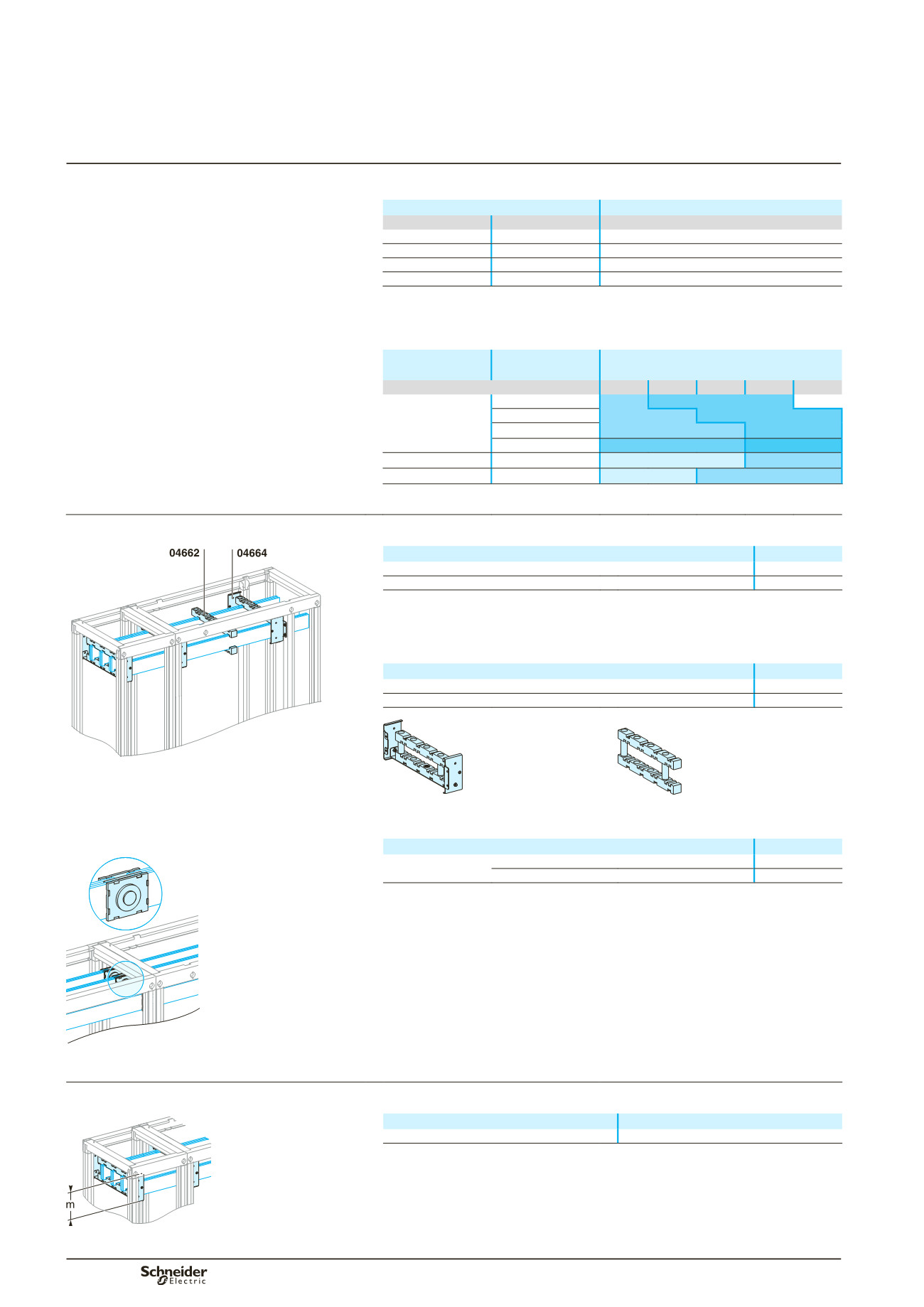
Busbar selection
Flat busbars, L = 2000 mm
DD381223
Designation
Cat. no.
Copper bar without holes, 60 x 5
04536
Copper bar without holes, 80 x 5
04538
Busbar supports
Two fixed supports for 650 mm, 650 + 150 mmwide frameworks and one fixed support
for 300/400 mm wide frameworks are mandatory. If more supports are required, use
free supports.
Designation
Cat. no.
Fixed support for horizontal bars
04664
Free support (additional)
04662
DD381226
DD381225
.
Icw 30 kA rms / 1 s.
04664.
04662.
.
Joints
Designation
Cat. no.
DD381227
1 joint for bars
W = 60 mm
04640
W = 80 mm
04641
Note:
when installed,at the bottom of cubicles, the busbars must be partitioned, see page B-28.
04640.
Busbar dimensions
DD381228
Type of busbars
No. of vertical modules required
Top or bottom horizontal busbars
3
Main distribution