


 333 / 338

D-99
Additional information
Practical information
DD383380.eps
Connection via the top
bb
Remove the roof.
bb
Drill the holes required to install cable glands or grommets.
bb
Install the cable glands or grommets. They must comply with the switchboard’s
degree of protection (IP).
bb
Refit the roof.
bb
Run the cables through the glands or grommets.
bb
Run the cables in the intended compartments and secure them to cable tie-bars
every 400 mm.
bb
Crimp the lugs and connect.
bb
When sealing does not call for cable glands or when sealing is achieved by means
of foam, cables can be routed in a rectangular cut-out in the roof.
The removable cross-member simplifies insertion of cables in the cubicle.
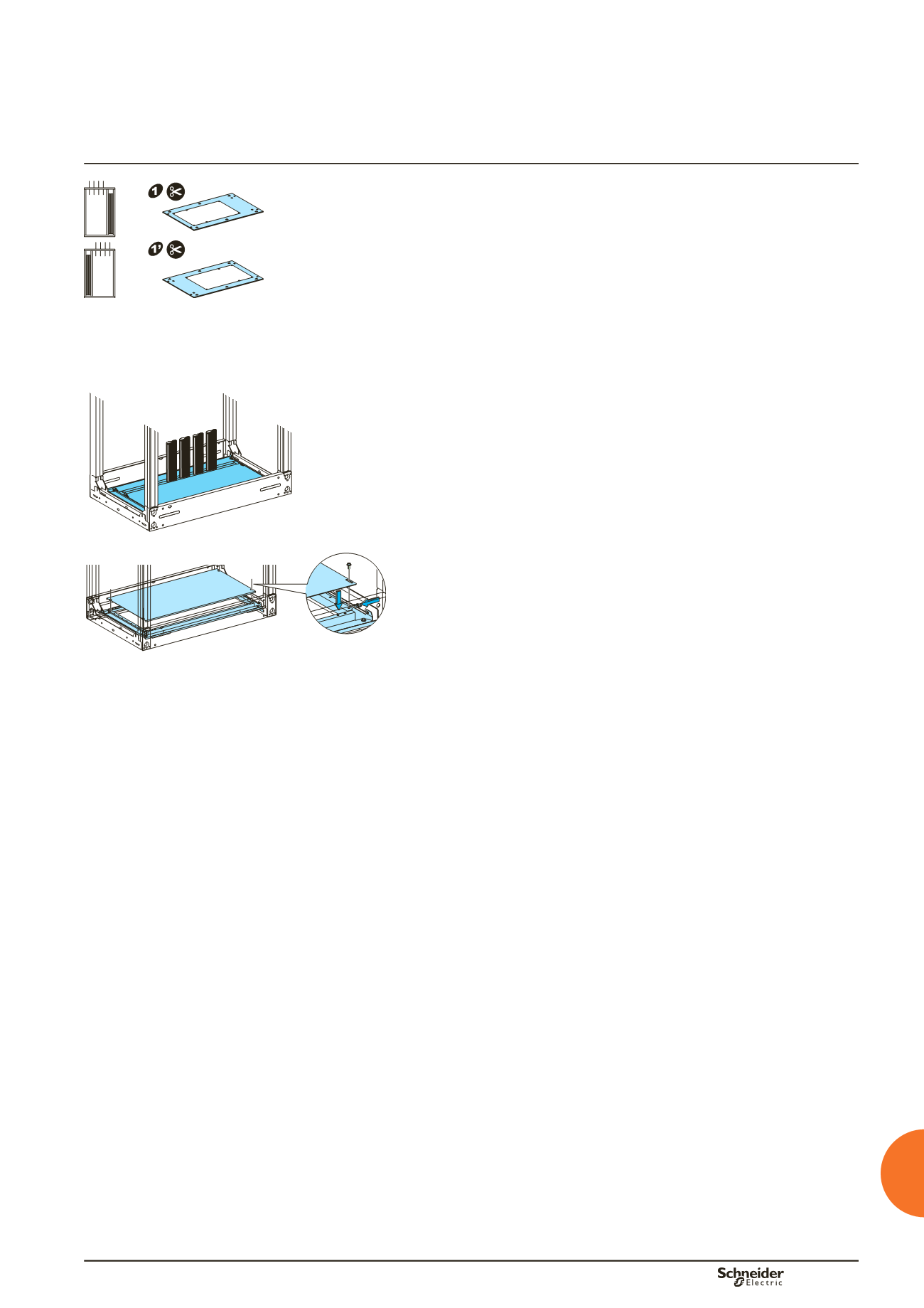
Connection via the bottom
Using a 2-part gland plate
bb
Drilling is not necessary with this type of gland plate.
bb
The gland plate avoids producing an induced current.
bb
The cables are protected by a polyurethane foam seal which provides a sealing
function.
Using a 1-part gland plate
bb
Remove the bottom plate.
bb
Drill the appropriate holes to assemble the cable glands or grommets (1-part gland
plates should not be drilled within 30 mm of the edges).
bb
Install the cable glands or grommets. They must comply with the required degree
of protection (IP).
bb
Refit the bottom plate.
bb
Run the cables through the glands or grommets.
bb
Run the cables in the intended compartments and secure them to cable tie-bars
every 400 mm.
bb
If cable glands are not used, it may be easier to prepare the cable terminations
outside the switchboard (e.g. lug crimping) and then to drop them inside the cubicle
having first disassembled the bottom removable cross-member.
Covering an incomer
For Masterpact NW/NT/NS1600b-3200 / Compact NS630b-1600
bb
Disassemble the cover plate to access to the device connection terminals.
bb
Connect the cables, respecting the required electrical clearances.
bb
Cut out the part of the cover disassembled in order to let the cables pass through
it, while preserving the necessary degree of protection.
DD210587.eps
DD383377.eps
Connection of power cables