


 120 / 130

120
®
(vi) Spacing of supports
Services support installations are usually considered as
multi-span arrangements but it is important to recognise that
the loading capability of the system is not uniform from end-to-
end. The strength of the two end spans in any run is much lower
than that of intermediate spans, even when the ends are rigidly
fixed. In many situations the end spans will be more lightly loaded
anyway; if however they are not and the installation will be fully
loaded from end-to-end then it is recommended that the support
spacing of both end spans should be reduced to no more than
three quarters that of intermediate spans. However it is not a
mandatory requirement, but is both useful and advisable.
Sometimes the necessary support spacing may be dictated by
the nature of the building fabric. If however the designer has
discretion over the spacing of supports the loading graphs can
be used to maximise this distance. This will reduce the number
of support components and fixings that will be required, thus
reducing the overall cost of the installed system.
Supports for cable tray (P2000)
Some of the Cablofil steel wire cable tray loading graphs are
denoted as P2000. This means setting supports at 2 metre apart
instead of 1.5 metres, thus enabling the installer to reduce,
a) the number of supports used and
b) the overall installation time.
Example:
Span 1500 : 100 m / 1.5 = 67 supports
Span 2000 : 100 m / 2 = 50 supports
Support of fittings
Cable tray fittings must always be provided with local support. The
illustrations opposite give recommended support positions.
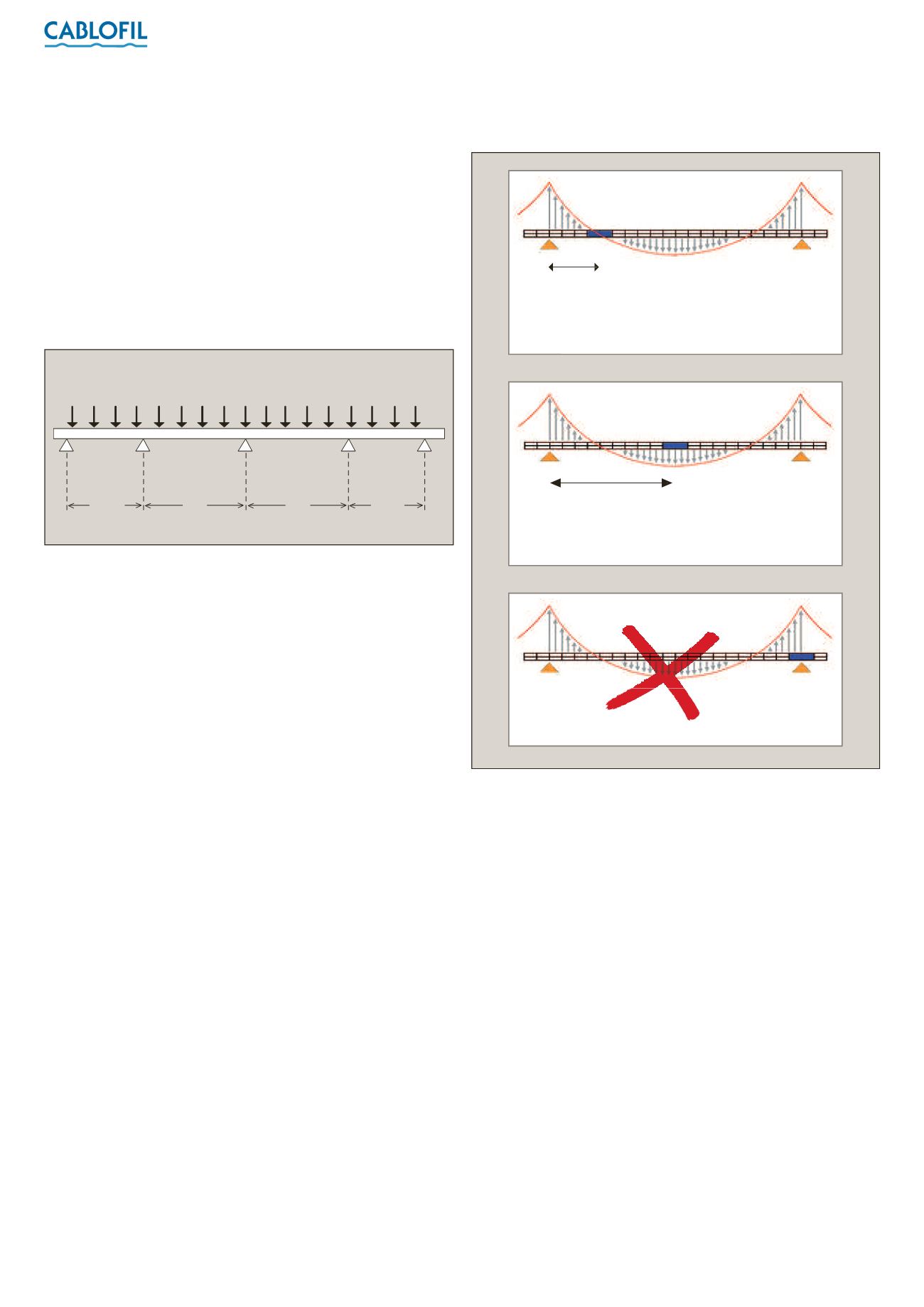
(vii) Location of couplers
In practice it is often impossible to predetermine where the
couplers will be located within a straight run of cable tray. However
it is well worth making some effort to roughly plan their position
during the early stages of installation.
The worst positions for the couplers is directly underneath
a support.
The best position for joints in a continuous installation is one
quarter / one fifth of the span distance on either side of each point
of support.
3 /4
S
S
S
3 /4
S
Fully loaded
Short
span
Short
span
Full span
Full span
L/2
Possible
70% PERFORMANCE
If the coupling is at L/2, a coefficient of 0·7 should be
applied to the permissible load
100% PERFORMANCE
For best results, place the couplers at 1/4 or
1/5 of the way along the span
Optimum
L/4 or 5
Forbidden
Never put the support under the coupler