


 122 / 130

122
®
(viii) Testing of cables within a support system
Short circuits
When an electrical short circuit occurs under fault conditions the
current that flows can, in some instances, reach tens of thousands
of amps and can last from a few milliseconds to several seconds
depending on the electrical installation requirements. Such short
circuit currents produce high magnetic fields which can interact
to produce large mechanical forces. These forces can cause
significant displacement of the cables and therefore some form of
restraint must be provided to prevent damage to the cables.
For large diameter cables the most common form of restraint is
by the use of cable cleats which hold the cables to the steel wire
cable tray. Some force may therefore be transferred to the steel
wire cable tray via the cable cleat, and could be sufficient to cause
damage to the steel wire cable tray.
The calculation of the forces is complex and the effect on a steel
wire cable tray system can only be fully determined by testing.
The main causes of short circuits are as follows :
• Damage to insulating material as a result of wear and tear or
mechanical impact
• Broken conductors
• Conducting elements falling onto or otherwise coming into
contact with the circuit
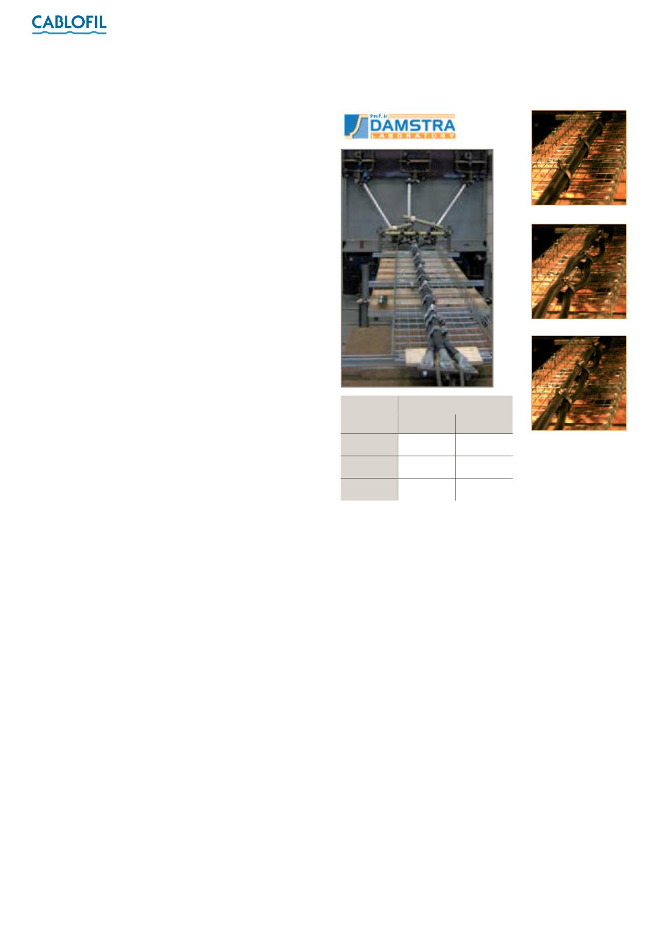
Short circuit tests
Tests were performed at a recognised independent laboratory
(DAMSTRA) and in accordance to standard EN 50368 (2003)
- Cable cleats for electrical installations, in order to validate
Cablofil steel wire cable tray’s mechanical resistance to the stress
generated by a short circuit.
An initial short circuit is generated during the tests, creating
mutual electromagnetic repulsion between the power cables.
The cable tray is then subjected to substantial mechanical stress
for a very short time (approx. one second).The process is repeated
in order to demonstrate that Cablofil steel wire cable tray is
structurally intact and able to cope with another short circuit.
As a final measure, additional tests are performed in a damp
environment to check whether the cables are fully intact.
The various tests are run with 3 successive levels of short circuit
current :
• 70 kA, equivalent to a repulsive force of 1300 daN
• 100 kA, equivalent to a repulsive force of 2700 daN
• 130 kA, equivalent to a repulsive force of 4500 daN
Material used : 3 m length of CF105/450, coupled 1/5 of the way
along the span, 5 fast couplers and a support span of 1·5 metres.
System configuration : 3 single conductor power cables, 38 mm in
diameter, are attached every 600 mm using cleats.
Conclusion
The tests reveal that the steel wire cable tray shows no permanent
deformation - its mesh structure is able to absorb the physical
stress generated by a significant short circuit current.
The cables remain intact in their original positions and network
availability is maintained.
After test
During test
Before test
Class
Intensity
Class 1
Class 2
70 kA
100 kA
130 kA