


 125 / 130

125
Results and interpretations
A simple comparison of the measurements for the different
cable tray configurations - steel wire cable tray (wire mesh) and
perforated cable tray, with and without cover - makes it possible
to quantify the role played by cable tray in relation to EMC.
These tests show that there is no significant difference in
‘Faraday cage’ effect offered by steel wire cable tray (wire mesh)
or perforated cable tray.
These results show that it is vital :
• to use metal cable tray
• to earth the cable tray
• to use a cover if required
• Test 2 - configuration:
Data cable alongside a power cable
A Category 6 UTP data cable is placed inside an insulated
anechoic chamber and subjected to an electromagnetic field
generated by a power cable.
The following parameters are studied :
• Cable tray earthing
• Separation distances – 0, 10, 20, 30 cm
• Cable tray type – steel wire cable tray (wire mesh), perforated
cable tray, trunking
• Separated cable trays
• One cable trays, with and without dividers
As a result, a total of 118 configurations are tested.
Results and interpretations
This second test configuration confirms that metal cable trays
reduce interference - steel wire cable tray (wire mesh) and
perforated cable tray.
To obtain a good EMC, these results show that it is vital :
• To use metal cable tray
• To earth the cable tray
2
Loadings
First and foremost, steel wire cable tray must act as an effective,
resistant and durable support for cables.
The mechanical performance of all products and accessories is
tested against the very demanding requirements imposed by the
international standard IEC 61537.
Generation of electromagnetic interference by
injecting current into the power cable.
Measurement of the interference generated in the data cable.
A comparison of the impact of 3 of the 118 configurations
Interference
within the cable
in dBµV
Frequency
i) Safe working loads
The permissable load stated in this catalogue represents the
load that Cablofil steel wire cable tray is guaranteed to be able to
bear. It assumes loads are evenly spread and is given in daN/m.
The standard permits a deflection equivalent to 1/100th of the
span. Legrand imposes a stricter limit of 1/200th for both safety
and aesthetic reasons. For example, Legrand voluntarily restricts
deflection to 10 mm for a span of 2 m, whereas the standard
would allow 20 mm.
Load tests carried out to IEC 61537 (safety factor 1·7 + joint
1
/
5 th
of the way along the span). Permissable load should include all
cable loads and any other additional loads (eg: wind, snow).
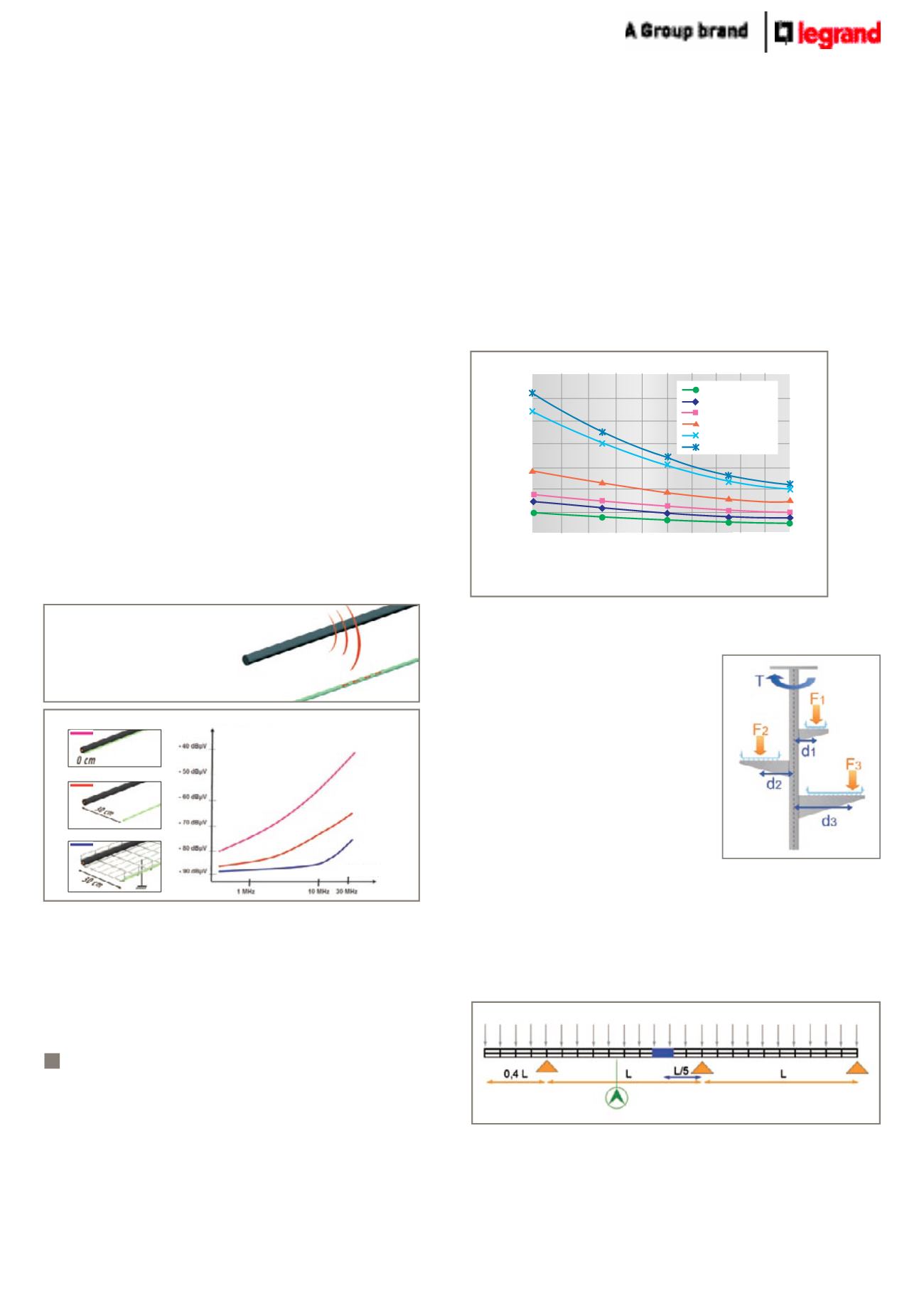
(ii) Safe working loads for supports
Brackets are classified by their permissible load (in daN).
Hangers are classified by their
permissible torque (in daN/m).
All Cablofil supports are tested and
comply with the IEC 61537 standard.
F
– is the load (in daN) applied to the
support.
d
– is the distance between the hanger
axis and the load.
T
– is the torque (in daN/m) applied to
the hanger.
Calculation rules :
Total F = F1 + F2 + F3
<
permissible
hanger load
Total T = F1.d1 + F3.d3 – F2.d2 < permissible hanger torque
(iii) Load tests : test configuration according to standard
IEC 61537
Each Cablofil steel wire cable tray has been tested in the required
configuration, with a coupling 1/5
th
of the way along the span.
Deflection is measured at the centre of the span.
The values given in this document have been obtained from
extensive testing of our cable support equipment. They are given
as a guide, so that customers may use Legrand’s products to
the best advantage; they are nevertheless average figures which
are given in good faith, but without accepting any liability in
contract, tort or otherwise in the event of different performance by
equipment which is actually supplied.
CF54 EZ, GC
Load (kg/m)
Span (mm)
100.0
140.0
80.0
60.0
40.0
20.0
0.0
2500
2300
2100
1900
1700
1500 1600
2000
1800
2200
2400
120.0
CF 54/50 to 100
CF 54/150
CF 54/200
CF 54/300
CF 54/400 to 500
CF 54/600
When the graph line is above the intersection of the required load and span lines,
the support equivalent is suitable for use within those load and span conditions.