


 119 / 130

119
(ii) Point loads
Point loads may consist of permanent equipment, such as lighting
luminaires, junction boxes or other switchgear, or temporary
loads such as commissioning equipment or installation personnel,
however, consider ‘safety during the installation phase’.
Analysis of uniformly distributed loads (UDL), such as cables or
pipes is relatively simple but analysing the effect of a point load
is quite complex; fortunately a simple alternative approach is
available.
Firstly, one makes the reasonable assumption that the point
load will be situated in the worst position at mid-span. The force
this point load imposes can then be taken as equivalent to that
imposed by a load of twice its value uniformly distributed along
the span. Thus the point load can be converted to the equivalent
uniformly distributed load which is then added to other UDL’s to
produce one total uniform load.
Example:
Point load = 30 kg
Support spacing = 3 m
UDL = 100 kg/m
UDL equivalent to 30 kg point load =
2 x Point Load = 2 x 30 kg = 60 kg = 20 kg/m
Total UDL = 100 kg/m + 20 kg/m = 120 kg/m
The suitability of a tray to carry this total load can then be
considered using the loading graph information (see p. 125).
Although this treatment does assume the point load will be in the
‘worst case’ position, the installer should, given discretion, always
position any point load as close as possible both to a support and
to either side flange, minimising the stress on the installation, as
per the following illustration.
(iii) Snow, wind and external forces
The loading graphs show the maximum safe working steady load
for each type of support system. If the system is outdoors and
must also sustain snow, ice, wind or other variable forces these
must also be taken into account at the design stage.
Appropriate design data for UK weather conditions is given in
British Standard BS EN 1991.
(iv) Safety factor
To arrive at a safe working load (SWL) for each type of equipment
Legrand test their products to find the ultimate failure load. The
SWL is obtained by dividing the load before failure by a factor of
1·7 minimum.
This safety factor may need to be increased by the designer
depending upon the circumstances. For example, if the support
system is expected to be subject to aggressive abuse a safety
factor as high as three or more may be used. Such treatment is,
however, the exception and care should be taken not to
over-design the system by using an unnecessarily high
safety factor.
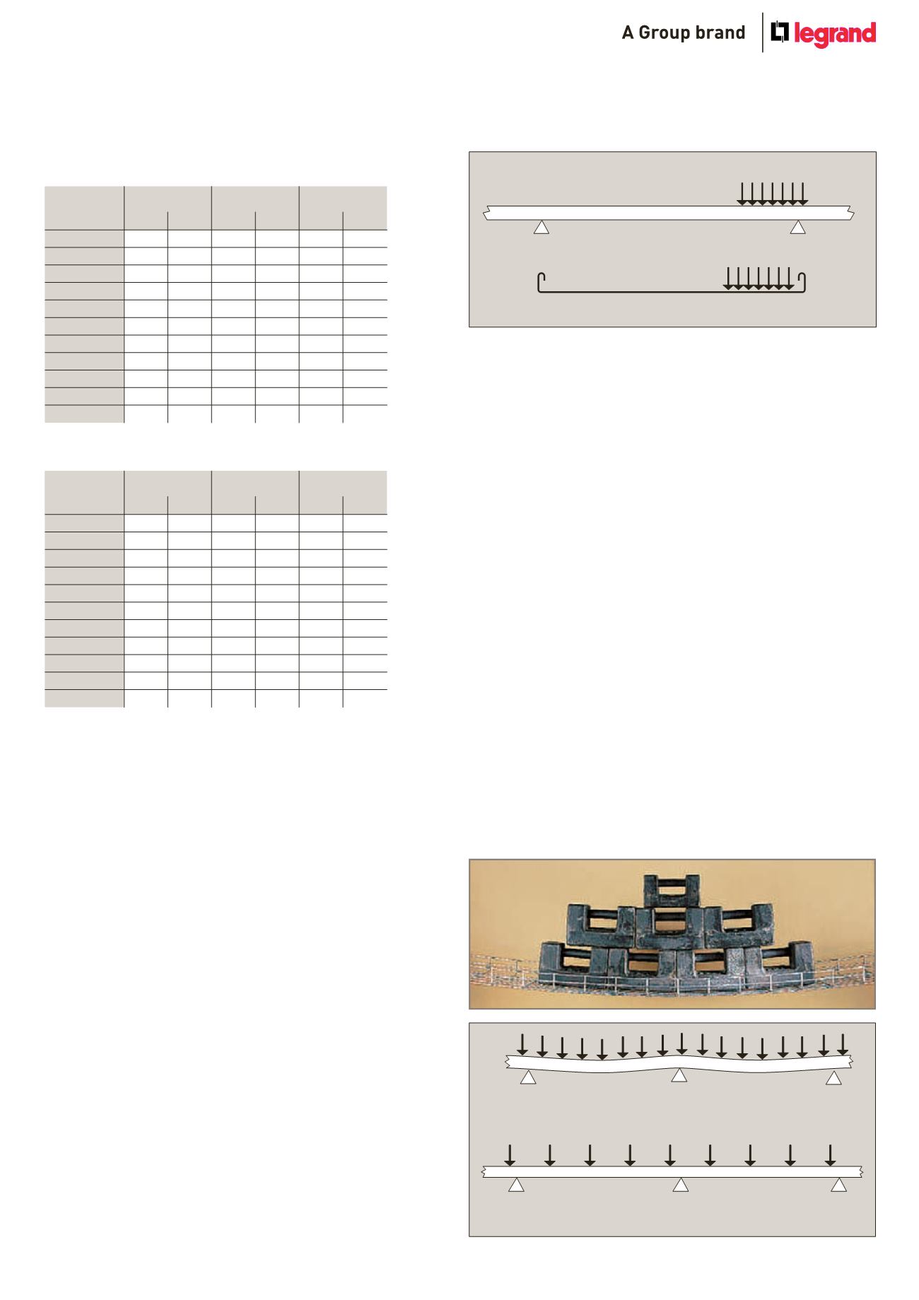
(v) Deflection
The deflection of a cable tray under load is not directly related to
its strength but it is obviously of aesthetic importance. For this
reason it may be necessary to estimate the likely deflection whilst
designing an installation, especially if it will be in a highly visible
location. Experience has shown that in order to maintain a degree
of deflection which is subjectively acceptable to the eye, the load
on the cable tray will often be restricted to well below its safe
maximum.
In the event of critical overload, a steel wire cable tray (wire mesh)
structure becomes like a hammock.
W
W
Table 3 : PVC unarmoured stranded copper power
cables to BS 6346
Nom. area
2 core
3 core
4 core
of conductor
(mm
2
)
kg/m D in mm
kg/m D in mm
kg/m D in mm
25
0·7
18·4
1·0
20·4
1·3
22·7
35
0·9
20·0
1·3
22·4
1·7
25·0
50
1·2
22·2
1·7
25·4
2·3
28·6
70
1·7
24·6
2·4
28·4
3·1
32·2
95
2·3
28·2
3·3
33·1
4·3
37·2
120
2·8
30·9
4·0
36·0
5·3
40·6
150
3·5
34·1
4·9
39·7
6·5
45·0
185
4·2
37·8
6·1
44·1
8·0
49·8
240
5·5
43·2
8·0
49·6
10·6
56·2
300
7·0
47·2
9·7
55·0
13·2
62·5
400
8·5
53·2
12·6
61·4
16·7
69·6
Table 4 : PVC armoured stranded copper power cables
to BS 6346
Nom. area
2 core
3 core
4 core
of conductor
(mm
2
)
kg/m D in mm
kg/m D in mm
kg/m D in mm
25
1·3
23·0
1·7
25·1
2·1
27·5
35
1·6
24·8
2·1
27·3
2·6
30·0
50
2·0
27·2
2·6
30·5
3·5
34·8
70
2·5
29·5
3·6
34·8
4·5
38·4
95
3·5
34·4
4·6
39·1
5·9
43·3
120
4·1
37·1
5·5
41·9
7·5
48·1
150
4·9
40·2
7·0
47·2
8·8
52·3
185
6·3
45·1
8·4
51·4
10·7
57·5
240
7·8
50·5
10·7
57·3
13·5
63·9
300
9·3
55·4
12·7
62·6
16·4
69·9
400
11·3
60·8
15·7
68·8
21·3
78·8
Reduce load to reduce deflection
Safe, but visually unacceptable