


 293 / 430

6.21
Sales Service Centre • 01952 675612 Technical Support Helpline • 01952 675689
Topology of the System
Topology and architecture of a system
Each installation consists of input and output products which can be
wire or radio.
For wire products, a TXA111 bus supply must be installed.
Media and communication support :
• Wire products : use of the bus cable (2 x 2 x 0,8mm)
• Radio system : the link is done by 868 MHz reserved
radio frequency
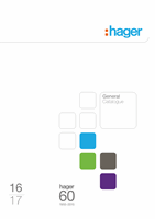
Topology 1 : Wire installation
Each Tebis product can exchange Information with all other Tebis
products connected to the bus cable. Supply of bus is done in
continuous 30V DC SELV.
The right side outline gives the maximum lengths of the bus cable
with a TXA111 supply.
The following values must not be exceeded :
• Total maximum length : 1000m
• Maximum distance between twisted pair 2 products : 700m
• Maximum distance between supply and a product : 350m
The above data define an EIB line. Each EIB line needs a supply and
can have up to 64 communicating products.
Role of the TYF130 line coupler
The line coupler “expand” and put back into form the signals on the
bus cable and allow to extend the system. Thanks to the coupler the
primary line can be extended up to 3 times.
Maximum limit of an “extended” line:
The diagram on the right shows the maximum limits of the system
with 4 supplies and 3 line couplers. The lengths of different
elementary lines remain the same but at the end, the following
• Total maximum length : 4 x 1000 m
• Maximum distance between 2 products on the same line :
700 m
• Maximum distance between supply of an elementary line and any
product of the same elementary line : 350 m
You can thus install at the maximum 4 x 64 = 256 TX products
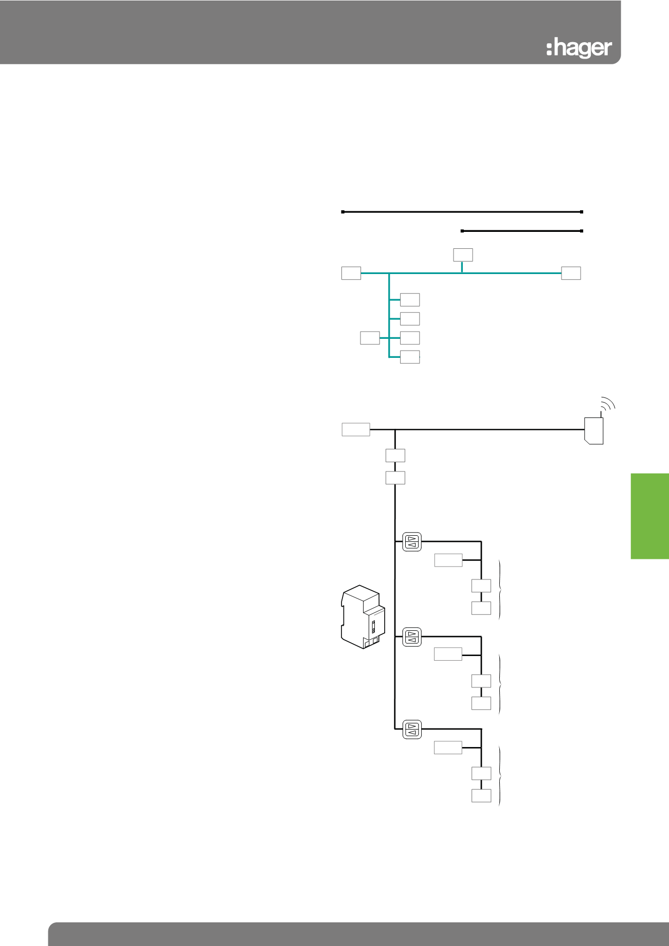
Role of the TR131A
In the configuration phase of the installation, the TR131A is the
interface between the TX products, connected among themselves by
the bus cable and TX100GB radio configuration tool.
After putting into service, the TR131A can be withdrawn and reused
to configure other systems.
Nevertheless in case of modification of the system or for
maintenance needs it will be necessary to reinstall again the media
coupler, that is why,
we recommend leaving TR131A in the system.
Several system architectures can be found :
1. fully wire systems
2. fully radio systems
3. combined wire and radio systems
The topologies corresponding to these 3 types of systems are
described below :
Tebis Wire System
Extension of a Tebis system using wire products
You can extend a line and install more than 64 products by using line
couplers and additional supplies (maximum 3).
Note: Power supplies do not count as product, but line couplers do.
700 m
TX
TX
TX
TX
TX
TX
TX
supp.
maximum accumulated length
of bus cable : 1000m
350 m
TR131A
media
coupler
TA 008
TX
TX
TX
TX
TX
TX
TX
TX
product 1
product 64
Supply
product 65
line
coupler
TA 008
product 128
line
coupler
TA 008
product 192
line
coupler
TA 008
product 66
product 127
product 129
product 191
product 193
product 256
primary line
extension n°1
extension n°2
extension n°3
Supply
Supply
Supply
In Tebis systems it is necessary to comply
withg the following rules for each line of the
64 products:
• Max 350M between supply and products
• Max 700M between 2 TX products
• Max 1000M accumulated length of all bus
cable segments on the line
Tebis KNX