


 644 / 759

 mkelectric.co.uk
644
CABLE MANAGEMENT
PERIMETER AND
DISTRIBUTION
Pinnacle Technical
COVERS
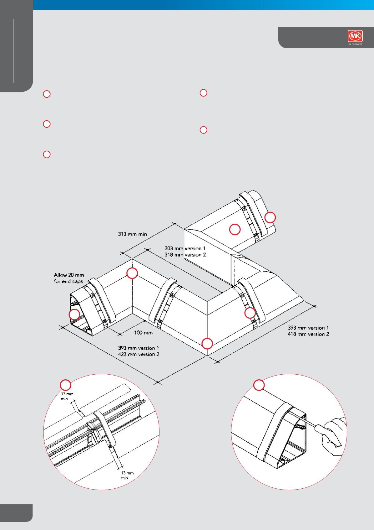
Slide cover under end cap where required before locating
correctly in position. Pushing firmly snap into place. The top
cover in the double (back to back) trunking locks the two
trunking bodies together.
Internal and external corner covers should be installed with
couplers. Leave a gap of 13mm at the junction between
corner cover and the trunking covers to allow fitting of coupler
covers. Correctly position and snap firmly into place.
At joint couplers, overlap the coupler carrier flanges with
the lids. The gap left between the covers will allow for
the fitting of joint covers. Having satisfactorily installed all
trunking covers firmly push fit the coupler covers into place
overlapping all the cover completely.
Removal – Main compartment cover removal is readily
achieved if a wiring accessory or coupler is present. Remove
the accessory and exerting pressure to the underside
of the cover with the head of a flat screwdriver to initiate
disengagement, peel the cover back.
When no accessory is available remove a moulded coupler
cover by placing the head of a small flat screwdriver at
the junction with the trunking cover and lever outwards
slowly disengaging the cover moulding. When levering off
coupler covers protect trunking faces from damage. When
the coupler cover is removed initiate clip disengagement of
trunking covers and peel back.
11
12
12
13
14
15
13
15
11
12
13
14
15