


 642 / 759

 mkelectric.co.uk
642
CABLE MANAGEMENT
PERIMETER AND
DISTRIBUTION
Pinnacle Technical
GENERAL NOTES
Prior to installation strike a line of trunking using a plumb and
chalk line for vertical, and spirit levels for horizontal runs.
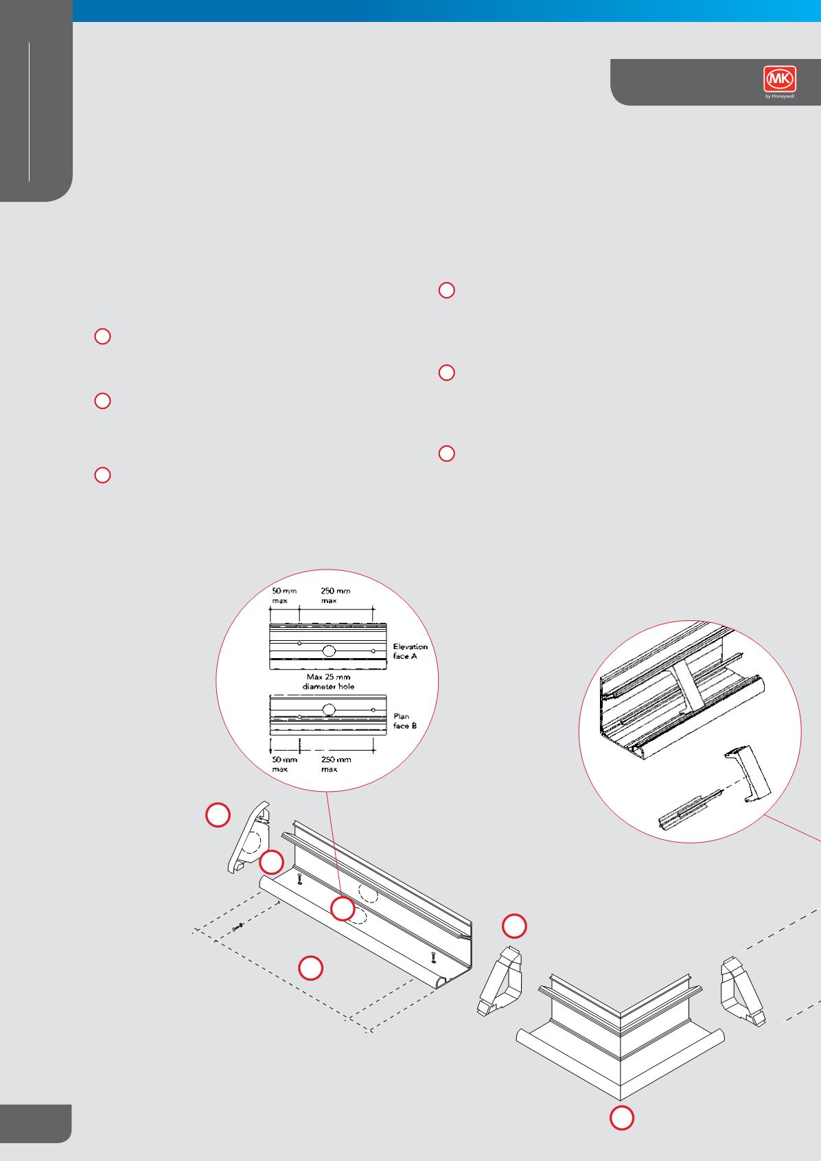
INCOMING SUPPLY CABLES
Establish location of incoming cable supplies. Entry into
the trunking can be from the back, base or end caps and is
achieved by drilling up to a 25mm hole using the drill base
centres in the trunking and inserting a conduit gland.
Holes of 20mm can be drilled into the end caps for access
to the large compartment using one of a series of moulded
drill centres.
FIXING
Trunking requires fixing at staggered centres, 250mm
maximum along the length with the first and last fixing not
more than 50mm from the end of each length. Drill trunking
with 6mm holes using drill guides and fix with pan or round
head screws and washers (Note: Tighten screws firmly and
back off slightly to allow for movement). For double trunking
installation fix both bases this way.
Couplers – Always use a trunking coupler and cover at the
junction between each length and at corners to maintain IP4X
Classification. To fix push the coupler carrier onto the end of
the free trunking length. Slide up to fixed trunking and push
home.
Internal and External Corners – Remove covers. Push a
coupler onto each end and assemble to trunking. Position
trunking and corner. Check that the internal corner base
fits snugly into the corner. Fix trunking base as previously
described.
End caps – Having located the length of trunking and cut if
required push fit the end cap firmly onto the trunking ensuring
that it is butted up tight. Note: where greater retention is
required use MK adhesive EW PLUS to bond the end cap to
the trunking base only. Avoid adhesive contact with covers.
1
2
3
4
5
6
50mm
250mm
50mm
1
2
3
4
5
6
Installation Guide