


 638 / 759

 mkelectric.co.uk
638
CABLE MANAGEMENT
PERIMETER AND
DISTRIBUTION
Powerlink Plus
Technical
Installation Guide Continued
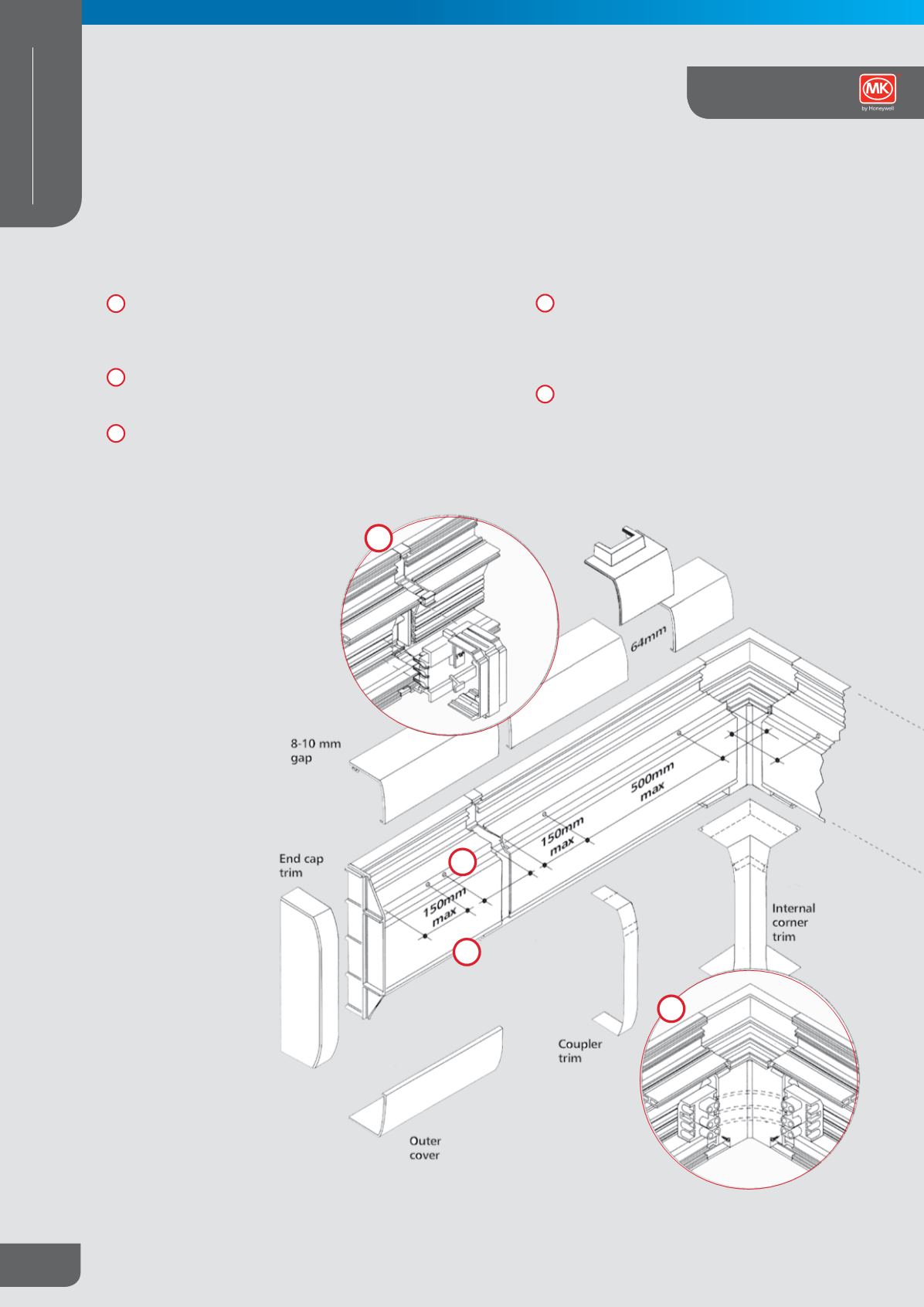
Cut central cover to length to fit exactly between the exposed
frontplates of accessories. At coupling positions leave
expansion gaps by cutting the central cover to the same
length as the trunking base.
Secure centre covers to the main base with the screws
provided every 500mm max, top and bottom and within
150mm of accessories and fittings.
At the junction of two adjacent lengths of trunking busbar
plug in the coupler to maintain electrical continuity. It is fitted
over a protector in the coupler carrier.
Data / Telecoms Devices – Secure enclosure box
over centre compartment with screws supplied.
Run cabling into enclosure and terminate onto outlet
on frontplate. Secure front cover to enclosure box
with screws provided.
Internal and external corners – Connect the lengths
of busbar using the cable link assembly (1919) and
secure trunking using the screws provided.
12
13
14
16
15
12
13
14
16
Skirting and Dado Trunking System