


 636 / 759

 mkelectric.co.uk
636
CABLE MANAGEMENT
PERIMETER AND
DISTRIBUTION
Powerlink Plus
Technical
GENERAL NOTES
Prior to installation strike a line of trunking using a plumb and
chalk line for vertical, and spirit levels for horizontal runs.
Surface track accommodates 63 amp busbar with an integral
duct directly above mains.
Data and Telecom cables.
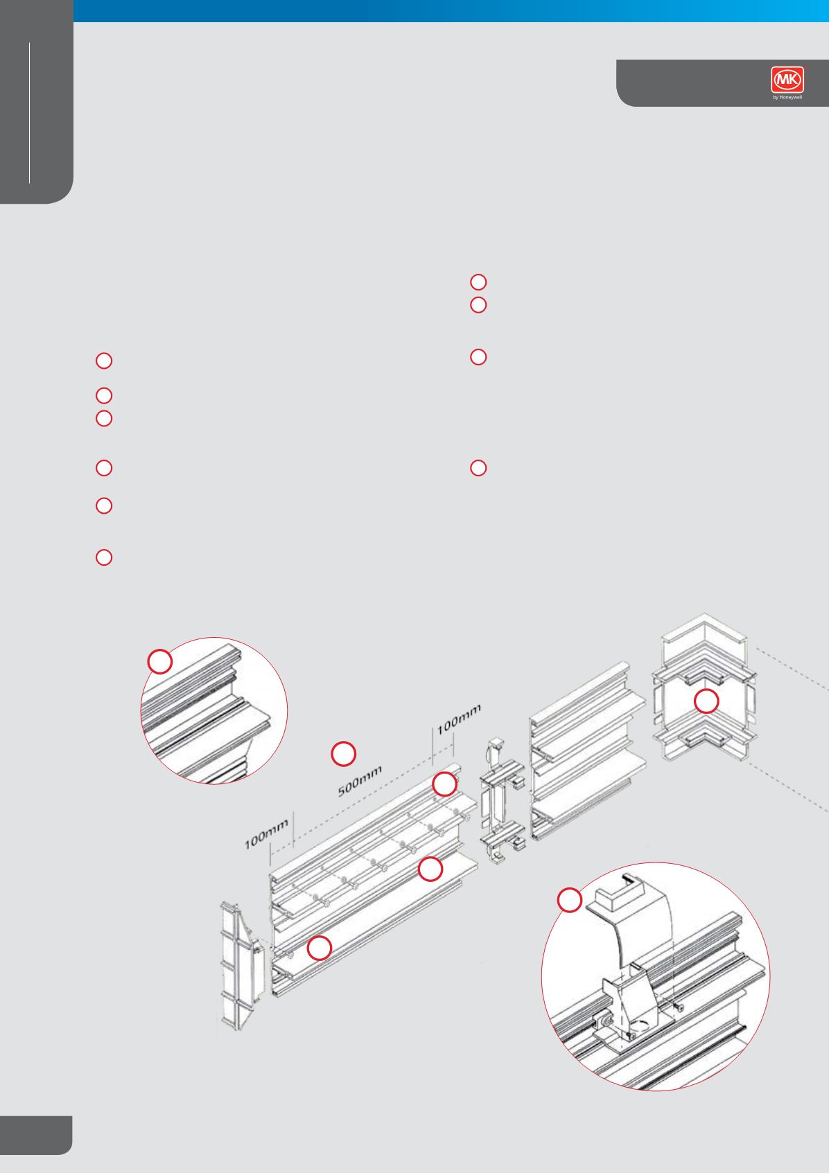
Pre cut slots and circular holes at 100mm centres permit
fixing holes to be drilled and a wallplug with screw inserted
after the surface track has been positioned.
When fixing trunking use bushes provided and No. 8 wood
screws.
Ensure trunking base is secured within 100mm from the end
and a maximum of 500mm apart on either side along the
length.
Check levels frequently – particularly at corners.
Debur all cut ends using a file or a sharp knife.
For mini trunking adaptors drill a 20mm diameter hole
through the wall of the centre compartment using drill
guide. Insert the tunnel and fix with two screws provided.
Bridging busbar compartment – if required to take
cables from top compartment to bottom or vice versa
– drill holes to align with top and bottom holes of the
centre compartment. Cut out 85mm from the busbar
at the required position. Install cable link (1919) to the
busbar and snap fit cable crossing barrier (K1937CHA)
over cables.
Commence installation at cable entry position. Route
cables into the central section, wire in to the selected
cable termination and plug into adjacent busbar and
secure with screws supplied.
Installation Guide
1
2
4
3
8
7
9
10
1
2
3
4
5
6
8
Skirting and Dado Trunking System
5
6