


 649 / 759

Technical Hotline
+44 (0)1268 563720
649
CABLE MANAGEMENT
PERIMETER AND
DISTRIBUTION
Premier Technical
A
20mm
D
D
E
E
C
B
A
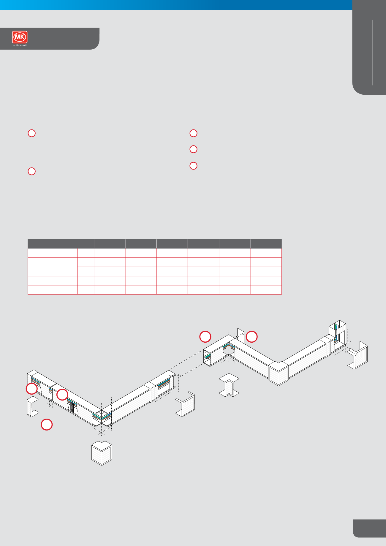
Clip in cable dividers prior to cabling. Divider clip fits to the
tee bar mounting rail extruded on the trunking base. To
correctly fit divider, the extension foot of the female clip
profile is mounted below the tee bar for horizontal runs, and
to the right hand side of vertical runs.
Cable retainers clip into the semi-circular grooves extruded
within the trunking profile. Retainers should be installed at
750mm maximum centres on straight runs or within 100mm
of each end, corner or change of plane.
AT INTERNAL CORNERS, EXTERNAL CORNERS, FLAT ANGLES AND
FLAT TEES, LEAVE GAPS BETWEEN LIDS AND THE END TRUNKING
BODY AS SHOWN BELOW:
Internal corners – measure distance into corner and cut
trunking length 2mm short.
Wall plates should be used to maintain enclosure function of
trunking.
Leave a gap of 20mm to allow fitting of joint cover moulding.
Installation Guide Continued
8
9
12
8
9
10
12
11
10
11
Integrated Trunking
50X50
75X50
75X75
100X40
100X50
100X100
EXTERNAL CORNER
A
62
62
87
52
62
140
FLAT TEE
B
74
99
99
124
124
124
C
65
90
90
115
115
115
INTERNAL CORNER
D
62
62
87
52
62
140
FLAT ANGLE
E
66
90
90
115
115
140