


 653 / 759

Technical Hotline
+44 (0)1268 563720
653
CABLE MANAGEMENT
PERIMETER AND
DISTRIBUTION
Norwich Technical
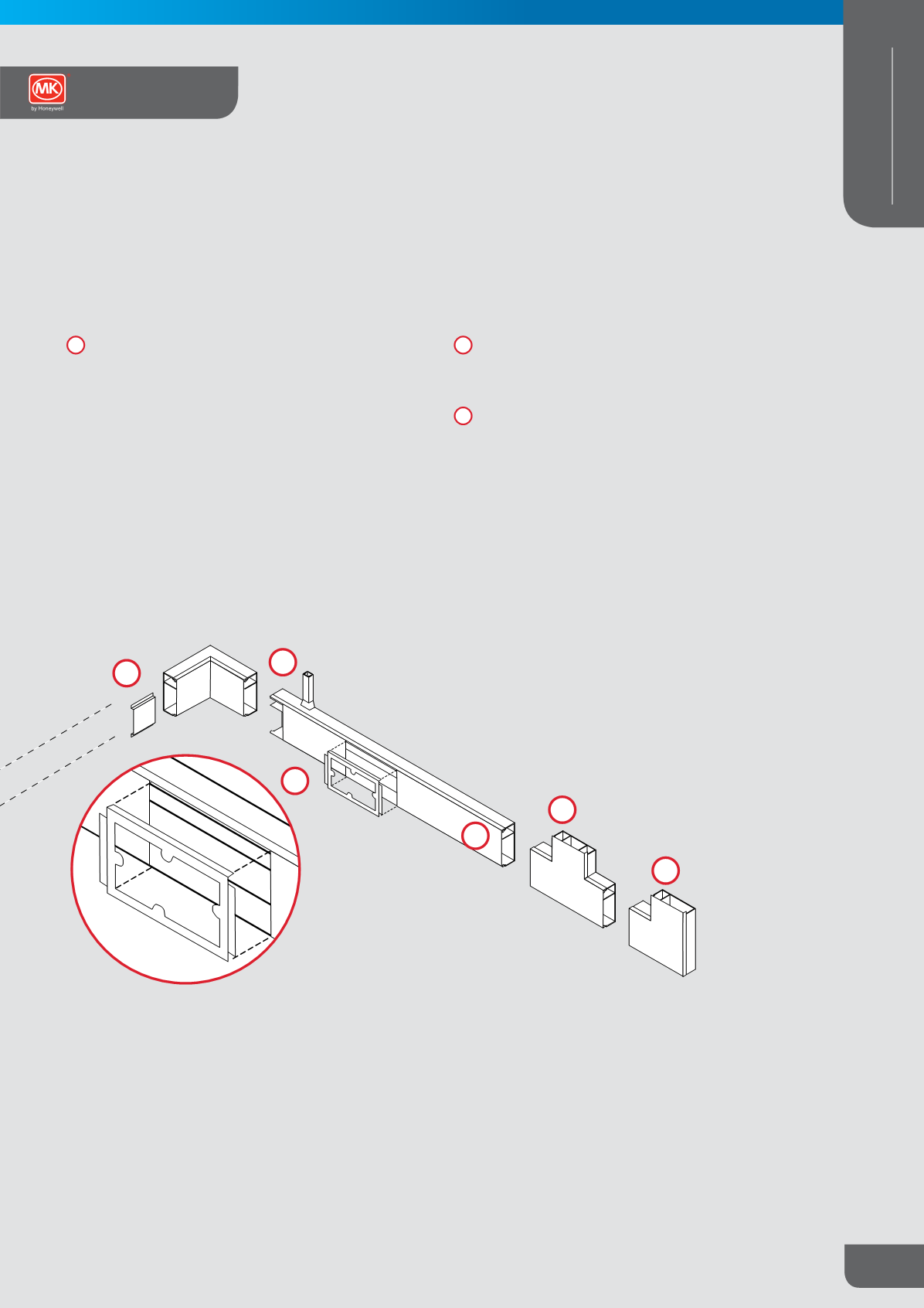
Junction with Mini-trunking
Locate the position of the junction. Drill the carrier with the
correct sized hole to accommodate the number of cables
required. Position the correct UEA/-adaptor using a short
length of compatible Mini-trunking as a guide.
The trunking should stop 6mm from the face of the Norwich
trunking to allow the adaptor to fit tight. Bond the adaptor to
the Norwich trunking using Egaweld PLUS solvent weld
Remove the temporary trunking guide and proceed with the
installation.
Cover
Covers simply clip onto base.
Accessories
The ‘clip on’ accessory mounting frames will accept most
standard one and two gang socket plates and socket
mounting with back box enables telephone circuitry to be
segregated from other services.
7
8
6
5
6
7
8
2
2
Trunking