


 506 / 582

BETA Monitoring
Monitoring of Plants and Devices
5
TT3 46 fault signaling units
14/10
Siemens ET B1 · 10/2008
14
The terminals A1, S1 to S4 and QH must be operated in-phase.
If no external acknowledgment key is connected, terminal QH
must be laid to L1.
If jumper X1 – X2 is fitted, open-circuit protection (otherwise
closed-circuit protection).
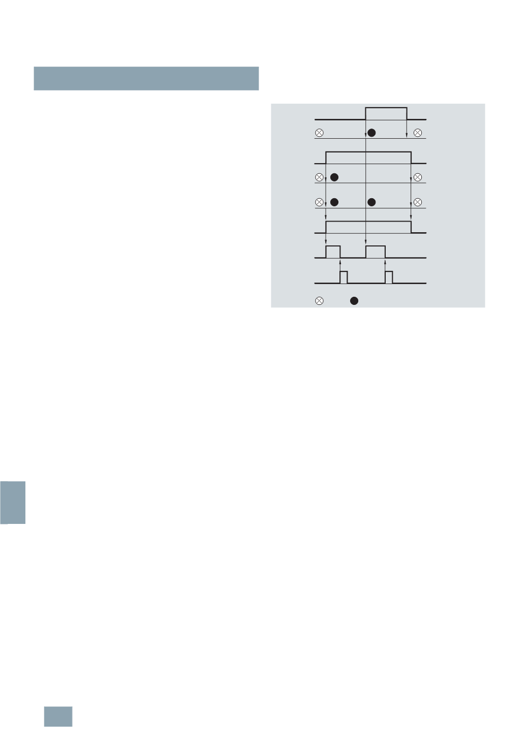
Contacts 13/14 and 23/24 close in the event of an incoming fault.
The assigned LED and the centralized fault indication LEDSM
light up.
The alarm sensor (contact 13/14) is switched off using the
acknowledgment key. The assigned LED and the centralized
fault indication LED continue to light up and contact 23/24
remains closed until the fault is eliminated.
Cables S and H carry an extra-low voltage. In the case of long
connections between different distribution boards a shielded
cable must be laid parallel to the installed load lines.
As a light signal sensor for the group messages, we recommend
devices 5TE5 7 or 5TE5 8; as alarm sensor, the devices
5
TT3 450 to 5TT3 453.
I2_07283c
Fault 1
LED 1
Fault 2
LED 2
Central indication
relay
Central indication
horn
Acknowledge.
horn
dark
bright
LED SM
© Siemens AG 2008