


 501 / 582

BETA Monitoring
Monitoring of Plants and Devices
5
TT7 1 GSM alarm modules
14/5
Siemens ET B1 · 10/2008
*
You can order this quantity or a multiple thereof.
14
■
Selection and ordering data
1)
Essential accessories.
■
Dimensional drawings
■
Schematics
U
e
I
e
U
c
MW DT Order No.
Price
per PU
PG PU PS*/
P. unit
Weight
per PU
approx.
V AC A AC V DC
Unit(s) Unit(s) kg
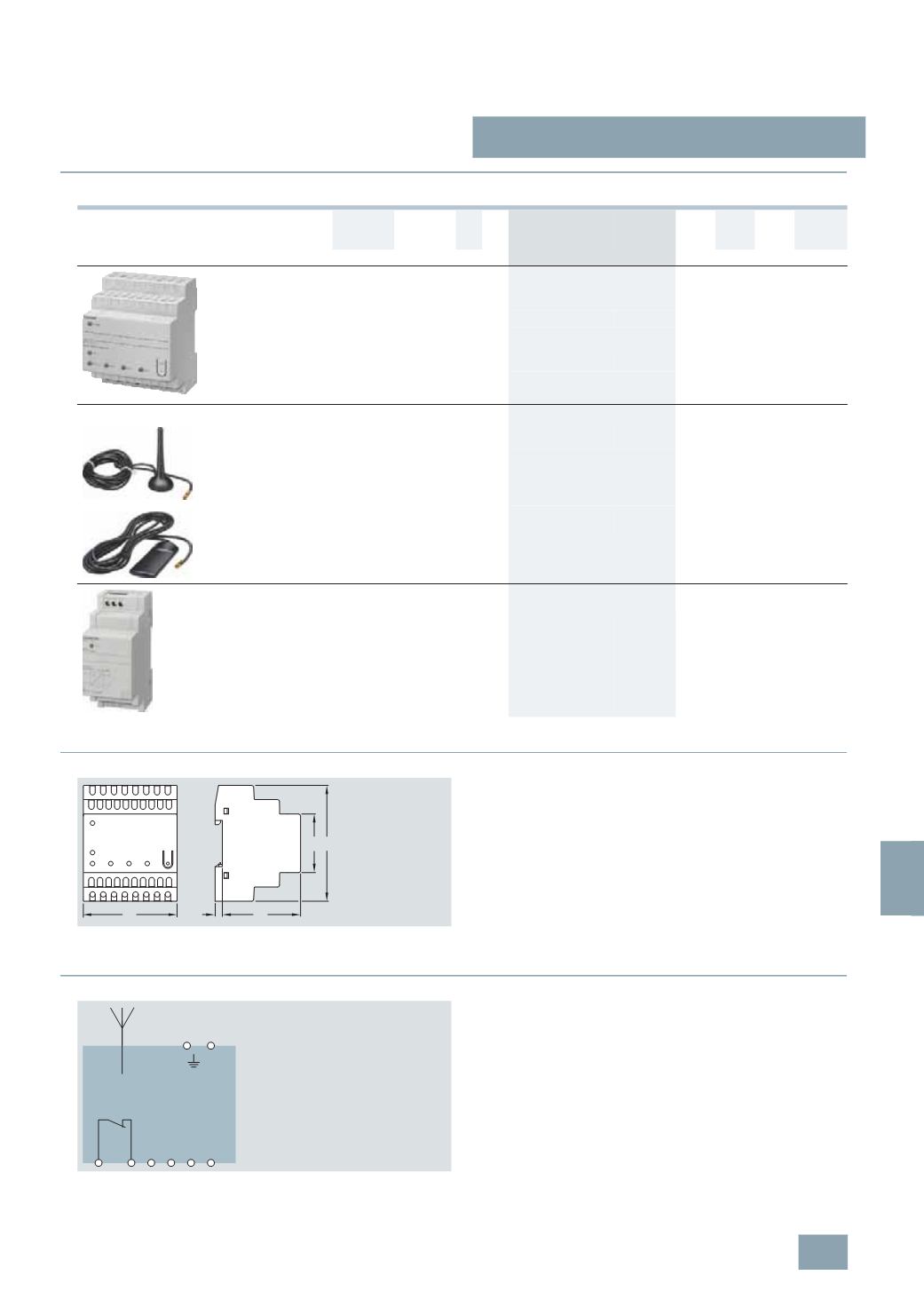
GSM alarm modules
For GSM network operating with two alarm inputs
and one switching output
230
5
24
4
A
5
TT7 110-0
027 1
1
0.205
•
With backup battery for signaling
in the event of power failures
230
5
24
4
A
5
TT7 120-0
027 1
1
0.250
Aerials
1)
Rod aerial with magnet base,
with MMC connection and connecting cable
B
5
TT7 908-1
027 1
1
0.070
Flat form for adhesion,
with MMC connection and connecting cable
B
5
TT7 908-2
027 1
1
0.050
Electronic power supply units
SELV, short-circuit resistant
For supplying the 5TT7 11 GSM alarm modules
within a supply voltage range of 150 V AC
to 230 V AC
For further information, please refer to chapter 10,
Transformers, Bells and Socket Outlets.
B
4
AC2 402
027 1
1
0.080
5
TT7 110
5
TT7 120
45
60
7
72
90
I2_12854a
5
TT7 110
5
TT7 120
3 4
DI1
5 6
DI2
7 8
D0
+24 V
1 2
I2_12852a
© Siemens AG 2008