


 502 / 582

BETA Monitoring
Monitoring of Plants and Devices
5
TT7 1 GSM alarm modules
14/6
Siemens ET B1 · 10/2008
14
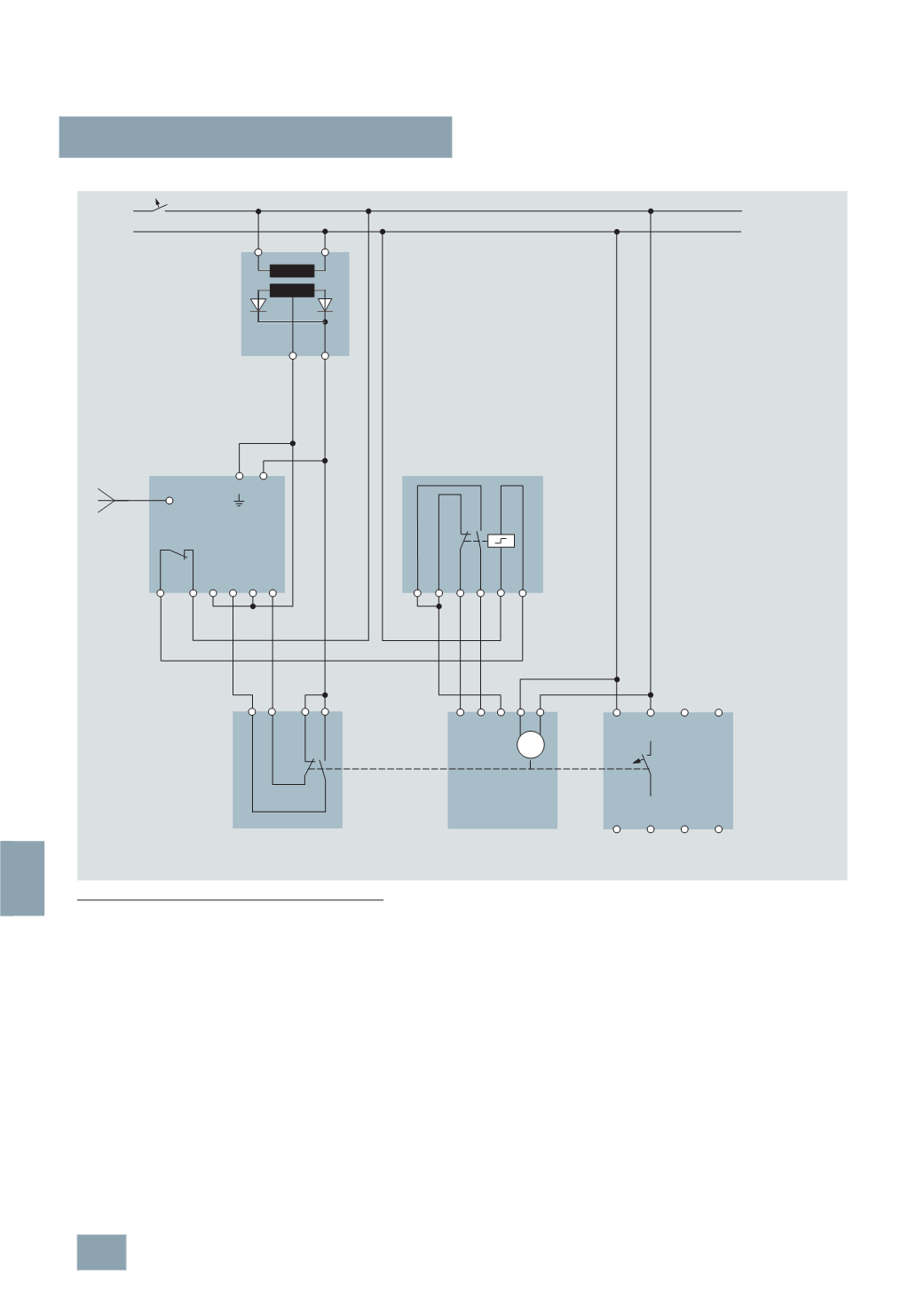
Switching example
Switching a 5ST3 051 remote controlled mechanism
•
The GSM alarm module sends an ON command.
•
The switching relay switches and sends this command to the
remote controlled mechanism, whereby the voltage at the
remote control switches the relay from the OFF to the ON input
over the changeover contact.
•
The auxiliary switch relays the ON position of the remote
controlled mechanism to the input of the GSM alarm module.
This sends the switching position ON per SMS.
N
L1
–
+
4
DI1
5 6
DI2
7 8
D0
+24 V
1 2
A1 A2 13 21 22 14
M
3 2
OFF ON
1
N P
N 5 3 1
N 6 4 2
13 21 22 14
3
I2_13381a
230
V AC
4
AC2 402
Power supply
5
TT7 110-0
5
TT7 120-0
GSM alarm
module
5
TT4 205-0
Switching relay
5
ST3 010
Auxiliary switch
5
SM3 346-6
RCCB
5
ST3 051
Remote controlled
mechanism
© Siemens AG 2008