


 508 / 582

BETA Monitoring
Monitoring of Plants and Devices
5
TT5 2 EMERGENCY-STOP modules
14/12
Siemens ET B1 · 10/2008
*
You can order this quantity or a multiple thereof.
14
■
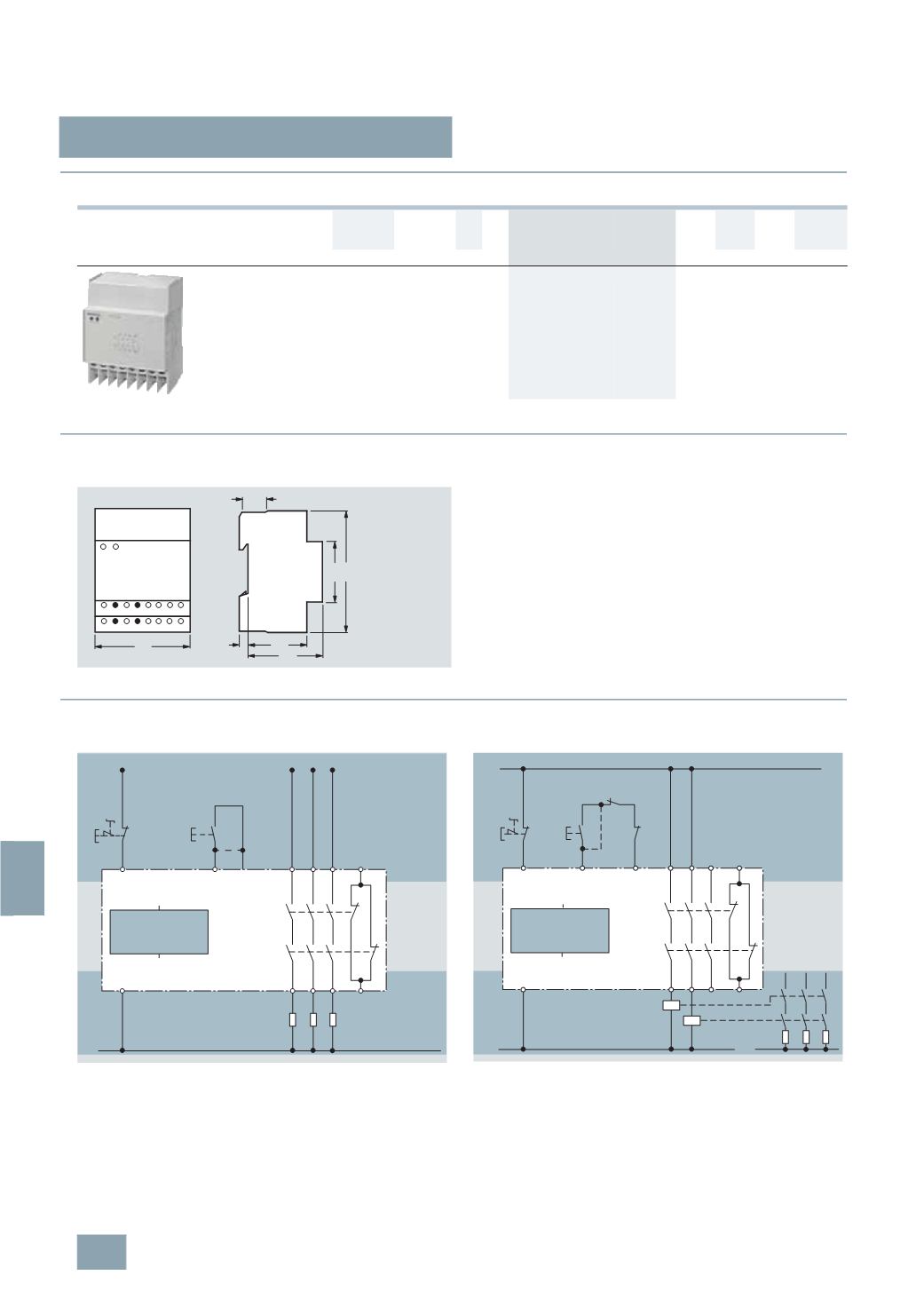
Selection and ordering data
■
Dimensional drawings
5
TT5 200 EMERGENCY-STOP modules
■
Schematics
Switching examples
Direct connection 230 V/400 V to 5 A
The monitoring logic checks internal relay contacts (not shown)
to see whether both relays have been released prior to switching
on. This ensures that no contacts are welded. The voltage level
at terminal A1 is also monitored. The parallel NC contacts K1
and K2 (terminals 41 and 42) can be connected as required.
Connection of external contactors
External contactors may be used when they are equipped with
positively driven contacts according to safety regulations
ZH1/457 of the German Trade Association. Contactors with
3
NO contacts and 1 NC contact must be used, whereby the
NC contacts must be integrated in the monitoring loop –
terminals Y1/Y2. The parallel NC contacts K1 and K2
(
terminals 41 and 42) can be connected as required.
U
e
I
e
U
c
MW DT Order No.
Price
per PU
PG PU PS*/
P. unit
Weight
per PU
approx.
V AC A AC V AC
Unit(s) Unit(s) kg
EMERGENCY-STOP modules
400
5
230
4
B
5
TT5 200
027 1
1
0.250
43
55
45
90
5
71
33
A2
13
Y1
16
Y2
23 41
34 14 24 42
K1/2
A1
I2_08437
Net-
work
L1
A1
Y1
13 23 33 41
14 24 34 42
K2
K1
A2
N
I2_08435b
Y2
EMERGENCY-
STOP
Monitoring
logic
On
L1
A1
Y1
13 23 33 41
14 24 34 42
K2
K1
A2
I2_08436b
K3
K4
Y2
K4
K3
L1 L2 L3
N
N
EMERGENCY-
STOP
Monitoring
logic
On
© Siemens AG 2008