


 513 / 582

BETA Monitoring
Monitoring of Plants and Devices
5
TT3 435 level relays
14/17
Siemens ET B1 · 10/2008
14
■
Schematics
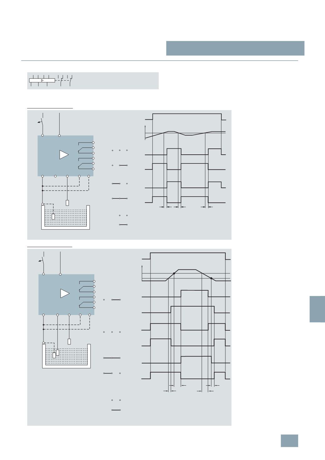
Switching example:
5
TT3 435
One-step level control
Two-step level control
X1
MINMAXCOM
X2 A1A2 14
11 21
12 2422
The one-step level control is
particularly suitable for dry run or
overrun protection with free
inflow/outflow.
The COM reference electrode and
the MAX electrode are required.
Without the jumper X1-COM only
relay 21-22-24 switches.
With the jumper X1-COM both
relays switch together.
21-24
21-22
21-24
21-22
COM X2
COM X2
MAX
0
11-14/21-24
11-12/21-22
t
11-14/21-24
11-12/21-22
COM X2
COM X2
t
t
X1
X1
X1
X1
COM X2
COM X2
I2_07520c
Supply
Level
Static current
Load current
L1
N
A1
A2
14
11
12
24
21
22
COM MIN MAX
X2
MIN
MAX
X1
I2_07518b
230
V AC
Level
t = t
v max
adjustable from 0.2 s to 20 s
The 2-step level control keeps the
liquid level between a minimum
and a maximum level.
Three electrodes are required:
MIN, MAX and COM.
Without the jumper X1-COM,
switching is as follows:
•
If the MAX level is fallen below/
exceeded, only relay 21-22-24.
•
If the MIN level is fallen below/
exceeded, only relay 11-12-14.
With the jumper X1–COM, both
relays switch together if the
MAX level is exceeded or the
MIN level is fallen below.
L1
N
A1
A2
14
11
12
24
21
22
COM
MAX
MIN
X2
MIN
MAX
X1
I2_07519b
Level
230
V AC
21-24
21-22
11-14
11-12
COM X2
MAX
U
0
MIN
H
1
2
X1
21-24
21-22
11-14
11-12
COM X2
min
X1
11-14, 21-24
11-12, 21-22
max
COM X2
X1
11-14, 21-24
11-12, 21-22
COM X2
X1
COM X2
COM X2
I2_07521c
t
v
t
v
min
t
v
max
t
v
Level
Static current
Load current
t
v max
and t
v min
adjustable from 0.2 s to 20 s
© Siemens AG 2008