


 515 / 582

BETA Monitoring
Monitoring of Plants and Devices
5
TT3 171 line circuit relays
14/19
Siemens ET B1 · 10/2008
14
■
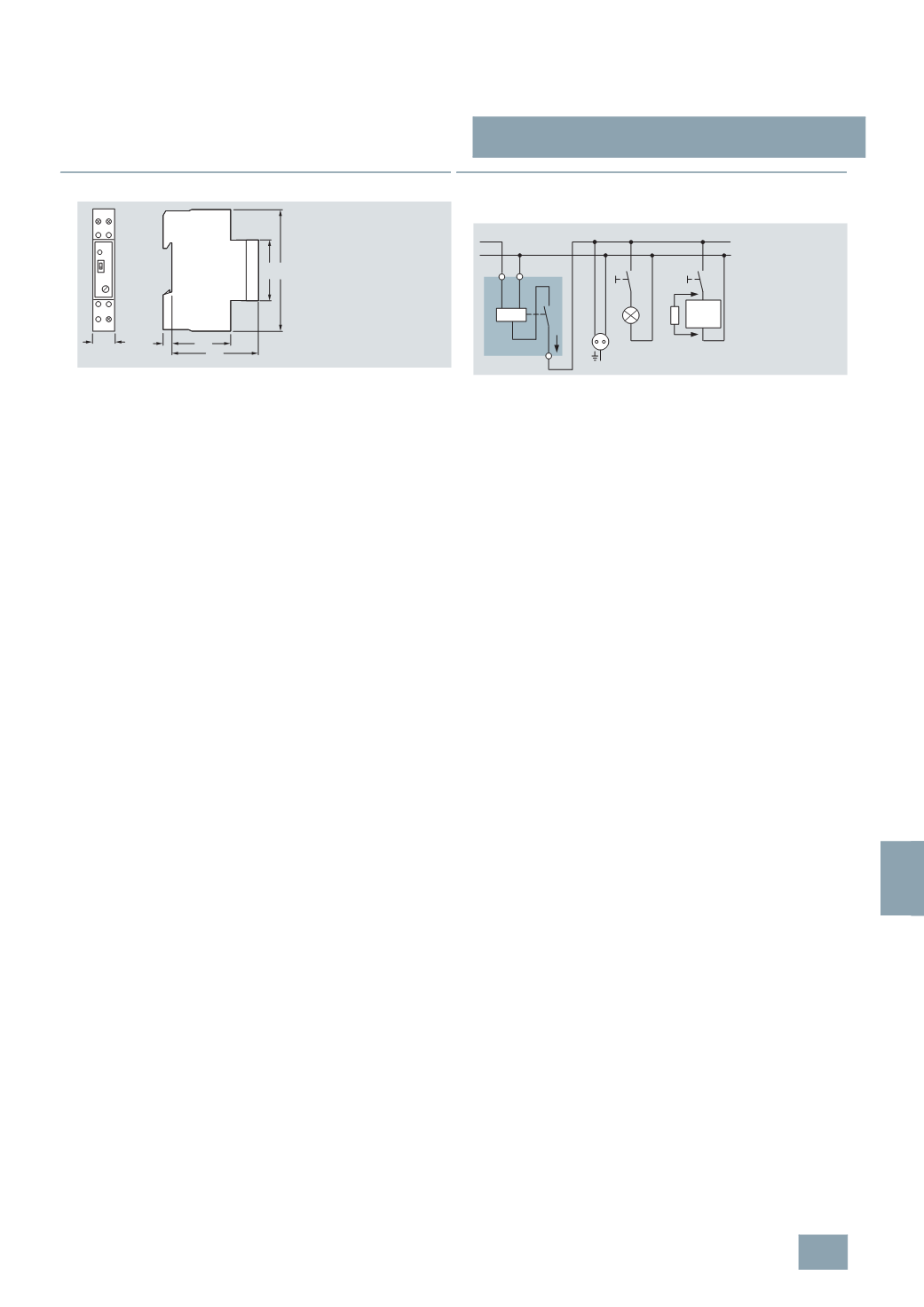
Dimensional drawings
■
Schematics
Switching example
If the line circuit relay does not respond to a load, it must be
connected with a 5TG8 222 base load resistor. Devices in active
standby operation may impair the function of the line circuit relay.
5
TT3 171
L N
5 43
64
18
I2_10775a
45
90
L N
L1
N
PTC
i
I2_07036b
230
V AC
Elec-
tronic
© Siemens AG 2008