


 518 / 582

BETA Monitoring
Monitoring of Plants and Devices
7
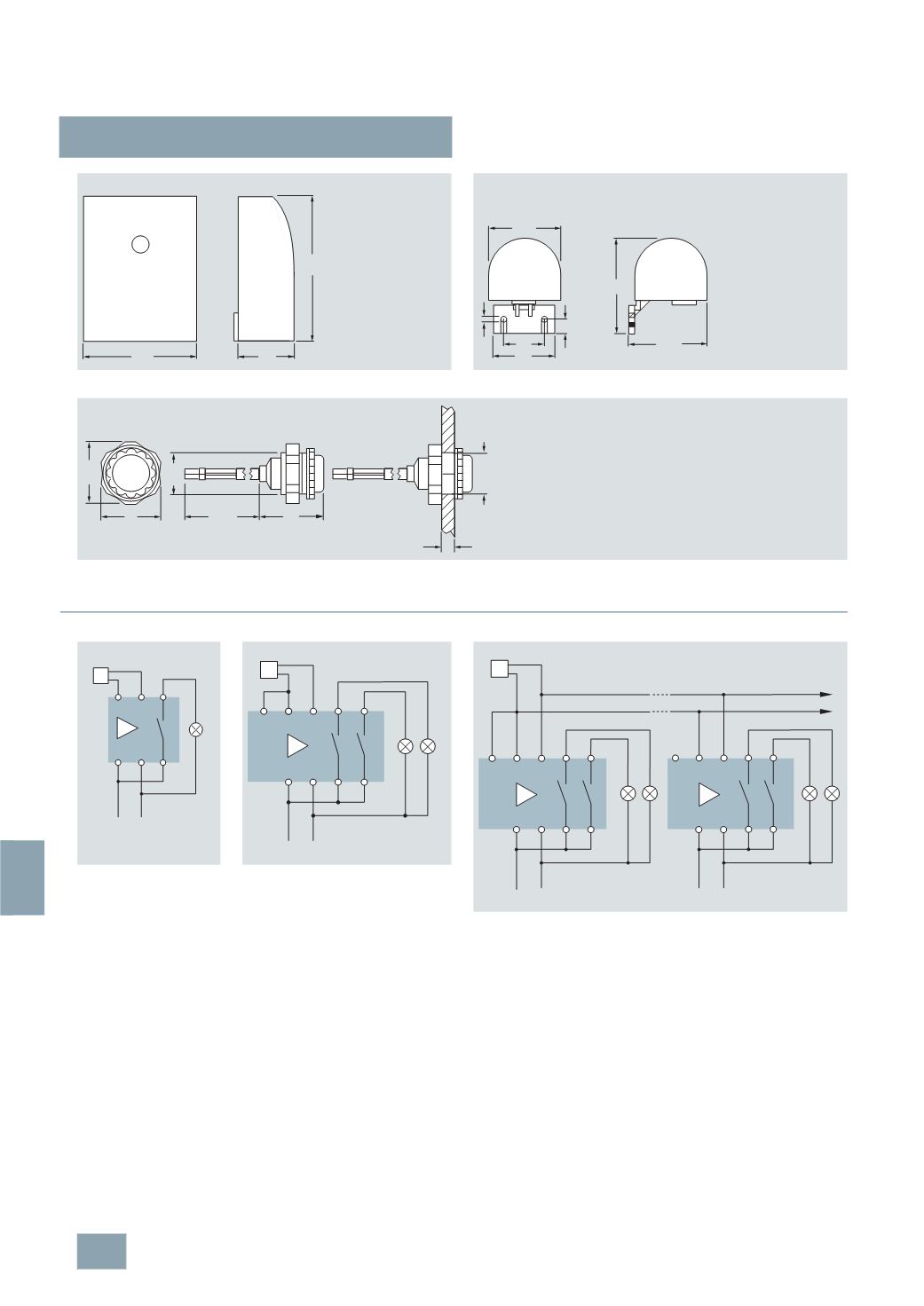
LQ2 1, 5TT3 3 dusk switches
14/22
Siemens ET B1 · 10/2008
14
■
Schematics
If the device measures a light level below the set value or if the
device is no-voltage, the contacts are in the position shown.
•
If the surrounding light level increases by approx. 30 to 100 %
above the set value, the light is switched off after the set delay
time.
•
If the surrounding light level falls below the set value, the light
is switched on after the set delay time.
5
TT3 303
7
LQ2 910
7
LQ2 911
80
40
105
I2_07133a
For surface mounting
I2_11328a
44
30
10
56,5
67
52,5
Ø
4
27
30
6
max
I2_11329b
1,5
m
Ø
20
Ø
29
Ø
20
+ 1
Dusk switches
7
LQ2 100
7
LQ2 102
Dusk switches
7
LQ2 101
7
LQ2 103
The cable length between the device and the light sensor must not exceed a
maximum of 50 m. The conductor cross-section must be a minimum of
2
× 0.75 mm².
Up to 12 dusk switches with a single sensor
7
LQ2 101
7
LQ2 103
Up to 12 dusk switches can be operated with a single sensor.
I2_11330b
1 2 4
9 10 3
L N
230
V AC
Sensor
I2_11331c
13 14 5 9
1 2 6 10
12
L N
Sensor
230
V AC
I2_11332b
1 2
12 13 14
L N
6
5
10
9
1
12 13 14
6
5
10
9
L N
2
230
V AC
230
V AC
Sensor
© Siemens AG 2008